
Uninterruptible Power Supply (UPS) Schematic
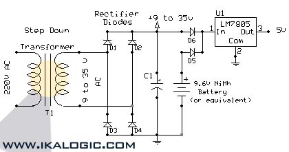
The circuit operates by utilizing a backup battery to maintain power supply during AC outages, which is crucial for sensitive electronic components that require a stable voltage. The core of this design is the voltage regulation and power management system that ensures a continuous 5V output. The capacitor C1 plays a vital role in smoothing out voltage fluctuations and providing additional current when needed, thus enhancing the circuit's reliability.
When selecting the capacitor, it is important to consider the Equivalent Series Resistance (ESR) as well, as a lower ESR will improve performance in high-frequency applications. The choice of a 9.6V NiMH battery is beneficial due to its ability to provide a stable voltage and sufficient current for the load. However, caution must be exercised when connecting a charger, as prolonged charging can lead to overheating and reduced battery life.
The integration of decoupling capacitors is essential for noise reduction and stability in microcontroller applications. Placing these capacitors close to the IC minimizes the effect of parasitic inductance and resistance in the PCB traces, ensuring that the microcontroller receives a clean power supply. Additionally, it is advisable to implement a diode or a similar component to prevent backflow of current from the battery to the AC supply, thereby protecting the circuit from potential damage.
In summary, this circuit design emphasizes the importance of reliable power delivery for sensitive electronics, with careful consideration given to component selection and layout to ensure optimal performance and longevity.This circuit will provide electric power from a backup battery when AC power is cut, always providing a clean 5V power supply for sensitive equipment like microcontrollers and logic circuits. The value of C1 is to be higher than 220 µF. The bigger the capacitance of this capacitor, the more power you can deliver to your circuits. The 9. 6 V NiMh Ba ttery can be replaced with any equivalent battery whose voltage is more than 7. 5V. A charger can be constantly connected to the battery from the same 220V source as the rest of the circuit, but depending on the battery and charger type, this procedure can shorten its life. For a clean transition from AC to Battery operation, especially with microcontrollers, use 10nF decoupling capacitors (ceramic capacitors) as near as possible from the concerned IC.
🔗 External reference
Related Circuits

Traditional soldering irons utilize mains AC supply for heating, which can be inconvenient in the absence of such a power source. This document describes a simple and cost-effective inverter circuit designed for use with standard soldering irons (25W, 30W,...
This software is highly effective, user-friendly, and enjoyable to utilize. It features an extensive library of symbols and includes a library editor for creating custom symbols. All drawings were completed before any soldering commenced, instilling confidence that all elements...
This chapter contains circuit diagrams for several power supplies designed for pulsed solid-state lasers. These include units suitable for driving the widely used Hughes ruby and YAG rangefinder laser assemblies, one utilizing the flash from a disposable pocket camera,...
Is the battery depleted, or is there an issue with the device? This question often arises when a battery-operated device, such as a Walkman, fails to power on. Before seeking professional repair services, it is advisable to first test...
Here is a 12 volt / 2 amp lamp dimmer that can be used to dim a standard 25 watt automobile brake or backup bulb by controlling the duty cycle of an astable 555 timer oscillator. When the wiper...
There are two systems of pneumatic central locking in vintage Audis. Earlier models are controlled by the driver's door lock, while later models use both front door locks. The earlier models (5000/100/200 before 1984, 4000/Coupe/Quattro/80/90 before 1988) utilize a...