
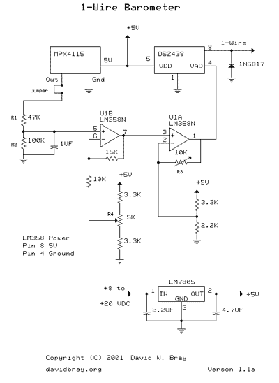
Barometer with Sensor Motorola MPX4115
The resolution of the barometric pressure is somewhat greater than ideal. With a pressure range of 28.0 to 31.0 inHg, the resolution is about 0.015 inHg. If a reduced pressure range of, say, 28.7 to 30.7 is tolerable, a resolution of 0.01 can be achieved. To allow for this high voltage, a voltage divider is used to bring the voltage down to the active range of 5-volt opamps -- this has a gain of 0.68.
This output is fed to an opamp stage, U1B, which has a gain of approximately 2.16. This stage has an adjustable voltage input which is added to the barometric sensor output within the opamp, thereby allowing the adjustment of the output voltage offset to the A/D converter. This in turn is fed to an opamp stage with a gain of U1A, capable of a gain range of 1/1 to about 8.58/1. The 10-turn potentiometers (pots) control the gain and offset. R3 controls the gain of U1A and R4 controls the offset of the output voltage. To see if the DS2438 is alive, connect the barometer to your 1-Wire adapter and run the iButton viewer. If it is alive you will see its 64-bit address (ID). Now to see if the barometer is alive -- if you did not set the 10K pot (R3), set it in the middle of the resistance range. With the barometer still connected to the 1-Wire adapter, in a MSDOS window run: baroCalibrate 3.25 1.25 31.0 28.0 baroCalibrate should show the adapter and COM port followed by a DS2438 device ID. It will give you a chance to select the correct DS2438 in case you have more than one on your 1-Wire network. Then it will display a continuous output of data from the DS2438. Turn the 5K pot (R4) until the Vad changes as the pot is turned. The output is fed to the 1-Wire DS2438 A/D.
The overall gain needed is about (3.25 - 1.25) / (4.25 - 3.79) = 4.4 at sea level, and (3.25 - 1.25) / (2.77 - 2.45) = 6.25 at 10,000 ft. The available overall gain is about 12.6 (i.e. 0.68 * 2.16 * 8.58).
Note that the MPX4115 feeds R1 through a jumper. This will allow easy change of input voltage from a source other than the MPX4115 for calibration. More resolution is not possible because the 5-volt MPX4115 has a range of 0 to 115 kPa (~0 to 34 inHg), the DS2438 is a 10-bit A/D but has a voltage range of ~1.5 to 10 volts, and normal operational amplifiers have a linear range of 0.75 to 3.5 volts (in 5-volt applications). Together, all three devices are somewhat incompatible for constructing a single 5-volt power supply barometer. By keeping the voltage to 5 volts, this allows the use of a Simon Hub.
The circuit design employs the MPX4115 pressure sensor, which outputs a voltage that varies with the atmospheric pressure. It operates within a specified current range and requires careful management of voltage levels to ensure compatibility with subsequent components. The use of a voltage divider is critical for scaling the sensor's output voltage to a level suitable for the operational amplifiers, which are configured to amplify the signal further.
The operational amplifiers (U1A and U1B) are configured to provide necessary gain adjustments. The gain settings are adjustable via potentiometers, allowing for fine-tuning of the output signal before it is sent to the DS2438 A/D converter. The DS2438 not only converts the analog signal to digital but also monitors battery conditions, integrating seamlessly into the 1-Wire network for data retrieval.
Calibration procedures are outlined to ensure accurate readings from the sensor, emphasizing the importance of the adjustable pots in setting the gain and offset parameters. This meticulous approach to calibration aids in achieving the desired resolution for pressure readings, which is critical for applications requiring precise atmospheric data.
The overall design reflects a balance between sensor capability, signal conditioning, and digital interfacing, ensuring that the output is both accurate and reliable within the constraints imposed by the components used.This design uses a Motorola MPX4115 Silicon Pressure Sensor, a Dallas Semiconductor DS2438 Smart Battery Monitor (to perform 1-Wire analog to digital conversion), an operational amplifier, a voltage regulator, a diode, and several resistors and capacitors. The circuit requires an additional power source other than that of the 1-Wire network. The MPX4115 requires about 7 ma of current. For barometric pressures the MPX4115 output voltage ranges from about 4.25 to 3.79 volts at sea level, and about 2.77 to 2.45 volts at 10,000 feet.
Most of this range is above the active voltage range of a 5 volt opamp circuit. In effect the sensor voltage is referenced to the power supply, not ground as desired. The resolution of the barometric pressure is somewhat greater than ideal. With a pressure range of 28.0 to 31.0 inHg the resolution is about 0.015 inHg. If a reduced pressure range of, say, 28.7 to 30.7 is tolerable a resolution of 0.01 can be achieved. To allow for this high voltage, a voltage divider is used to bring the voltage down to the active range of 5 volt opamps -- this has a gain of 0.68. This output is fed to an opamp stage, U1B, which has a gain of approximately 2.16. This stage has an adjustable voltage input which is added to the barometric sensor output within the opamp, thereby allowing the adjustment of the output voltage offset to the A/D converter.
This in turn is fed to an opamp stage with a gain of U1A, capable of a gain range of 1/1 to about 8.58/1. The 10-turn potentiometers (pots) control the gain and offset. R3 controls the gain of U1A and R4 controls the offset of the output voltage. To see if the DS2438 is alive, connect the barometer to your 1-Wire adapter and run the iButton viewer.
If it is alive you will see its 64 bit address (ID). Now to see if the barometer is alive -- if you did not set the 10K pot (R3), set it in the middle of the resistance range. With the barometer still connected to the 1-Wire adapter, in a MSDOS window run: baroCalibrate 3.25 1.25 31.0 28.0 baroCalibrate should show the adapter and COM port followed by a DS2438 device ID.
It will give you a chance to select the correct DS2438 in case you have more than one on your 1-Wire network. Then it will display a continuous output of data from the DS2438. Turn the 5K pot (R4) until the Vad changes as the pot is turned. The output is fed to the 1-Wire DS2438 A/D. The overall gain needed is about (3.25 - 1.25) / (4.25 - 3.79) = 4.4 at sea level, and (3.25 - 1.25) / (2.77 - 2.45) = 6.25 at 10,000 ft.
The available overall gain is about 12.6 (i.e. 0.68 * 2.16 * 8.58). Note that the MPX4115 feeds R1 through a jumper. This will allow easy change of input voltage from a source than the MPX4115 for calibration. More resolution is not possible because the 5 volt MPX4115 has a range of 0 to 115 Kpa (~0 to 34 inHg), the D2438 is a 10 bit A/D but has a voltage range of ~1.5 to 10 volts, and normal operational amplifiers have a linear range of 0.75 to 3.5 volts (in 5 volt applications). Together all three devices are somewhat incompatible for constructing a single 5 volt power supply barometer.
By keeping the voltage to 5 volts allows the use of a Simon Hub. 🔗 External reference
Related Circuits

This design circuit is for a temperature sensor that utilizes an LM335 integrated circuit (IC) to convert ambient temperature into an equivalent output voltage. The output voltage of the LM335 increases by approximately 10 mV for every 1 degree...
The Motion Sensor Switch circuit is an automatic water sprinkler controlled by a motion sensor, with the option to incorporate an alarm or light function. Before starting the construction, it is advisable to contact a local electronics component vendor...
The Thermistor, or NTC (Negative Temperature Coefficient) of 10K, is a standard type. Most types will work. The one in the diagram is a 10K model made by Fenwal (#197-103LAG-A01). The resistance lowers as the surrounding temperature increases, which...
The figure illustrates a multiple output crystal oscillator, which primarily consists of three gates of Al, four resistors, two capacitors, and a crystal. Resistors R1 to R4 offset two inverters within the linear range and are connected between pin...

The following circuit illustrates a 12-volt modular burglar alarm sensor circuit diagram. Features include a timed bell cut-off, as well as automatic exit and entry functions. The 12-volt modular burglar alarm sensor circuit is designed to provide effective security monitoring...
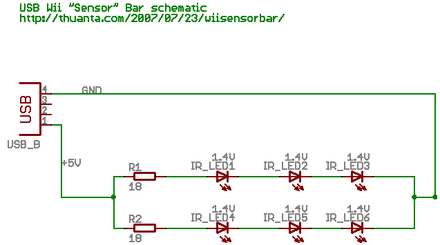
The following circuit illustrates the Wii "Sensor" Bar Project Circuit Diagram. Features include a series of infrared LEDs positioned at both ends of the bar, which emit infrared light. The Wii Sensor Bar is a crucial component for the Wii...
Warning: include(partials/cookie-banner.php): Failed to open stream: Permission denied in /var/www/html/nextgr/view-circuit.php on line 713
Warning: include(): Failed opening 'partials/cookie-banner.php' for inclusion (include_path='.:/usr/share/php') in /var/www/html/nextgr/view-circuit.php on line 713