Heat sensor relay switch
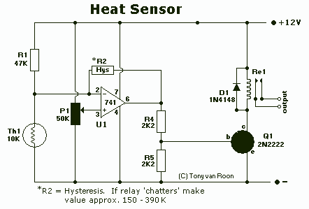
The Thermistor, or NTC (Negative Temperature Coefficient) of 10K, is a standard type. Most types will work. The one in the diagram is a 10K model made by Fenwal (#197-103LAG-A01). The resistance lowers as the surrounding temperature increases, which affects the output (pin 6) and energizes the small relay and Led1 (optional, just cosmetic and can be left out). P1 is a regular Bourns trimmer potentiometer and adjusts a certain range of temperatures. I used a 50K, 10-turn type for a bit finer adjustment but any type will work. R2 is optional in case your relays tend to 'chatter' a bit. It provides a bit of hysteresis when the set temperature of the thermistor reaches its threshold point. This value may need to be adjusted anywhere between 120K and 470K (although I indicated different values on the schematic). Transistor Q1 can be a 2N2222(A), 2N3904, NTE123A, ECG123A, etc. Not critical at all. It acts only as a switch for the relay so almost any type will work, as long as it can provide the current needed to activate the relay's coil. D1, the 1N4148, acts as a spark arrestor when the contacts of the relay open and eliminates false triggering. Feel free to use any other type, like a 1N4001 or something. Solder directly onto the '+' and '-' relay terminals.
The circuit employs a thermistor with a negative temperature coefficient (NTC) that exhibits a resistance of 10K at room temperature. This thermistor is sensitive to temperature changes, and its resistance decreases as the temperature rises, allowing for effective temperature sensing. The output from the thermistor is connected to pin 6, which serves as a control signal for activating a relay. The relay functions as a switch, controlling a load based on the temperature detected by the thermistor.
In the schematic, a Bourns trimmer potentiometer (P1) is included to allow for fine-tuning of the temperature threshold at which the relay is activated. A 50K, 10-turn potentiometer is suggested for precise adjustments, although any suitable potentiometer can be utilized. The optional resistor R2 is introduced to mitigate relay chatter, providing hysteresis in the system. This resistor can be adjusted within a range of 120K to 470K, depending on the specific characteristics of the relay being used.
Transistor Q1 is incorporated into the design as a switching element. Various transistor types such as the 2N2222(A), 2N3904, NTE123A, and ECG123A are suitable for this application, as the primary requirement is that it can handle the current necessary to energize the relay coil. The diode D1 (1N4148) is included in the circuit to serve as a flyback diode, protecting the circuit from voltage spikes generated when the relay contacts open. This diode can also be replaced with other similar diodes like the 1N4001, ensuring protection against false triggering due to inductive kickback from the relay.
The relay terminals are designed for direct soldering of the power supply connections, ensuring a reliable connection for activating the relay. The optional LED (Led1) serves as an indicator and can be included for visual feedback on the relay's status, though it is not essential for the circuit's operation. Overall, this circuit provides a robust solution for temperature-based control applications, allowing for customization based on the specific requirements of the implementation.The Thermistor, or NTC (Negative Temperature Coefficient) of 10K, is a standard type. Most types will work. The one in the diagram is a 10K model made by Fenwal (#197-103LAG-A01). The resistance lowers as the surrounding temperature increases which affects the output (pin 6) and energizes the small relay and Led1(optional, just cosmetic and can be left out). P1 is a regular Bourns trimmer potentiometer and adjusts a certain range of temperatures. I used a 50K, 10-turn type for a bit finer adjustment but any type will work. R2 is optional in case your relays tends to 'chatter' a bit. It provides a bit of hysteresis when the set temperature of the thermistor reaches its threshold point.
This value may need to be adjusted anywhere between 120K and 470K (although I indicated different values on the schematic). Transistor Q1 can be a 2N2222(A), 2N3904, NTE123A, ECG123A, etc. Not critical at all. It acts only as a switch for the relay so almost any type will work, as long as it can provide the current needed to activate the relay's coil.
D1, the 1N4148, acts as a spark arrestor when the contacts of the relay open and eliminates false triggering. Feel free to use any other type, like a 1N4001 or something. Solder directly onto the '+' and '-' relay terminals. 🔗 External reference
Warning: include(partials/cookie-banner.php): Failed to open stream: Permission denied in /var/www/html/nextgr/view-circuit.php on line 713
Warning: include(): Failed opening 'partials/cookie-banner.php' for inclusion (include_path='.:/usr/share/php') in /var/www/html/nextgr/view-circuit.php on line 713
