
Based LT3756 buck - boost mode drive circuit diagram
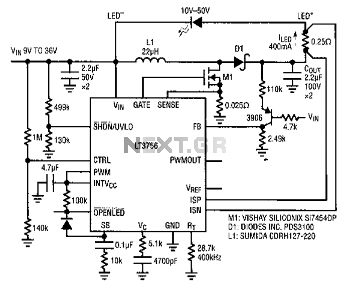
The described LED driver circuit operates in a buck-boost configuration, allowing it to efficiently regulate output voltage over a wide input voltage range. The design utilizes a single inductor to minimize component count, which is beneficial for reducing board space and overall system complexity. The input voltage range of 9V to 36V ensures compatibility with various power sources, including batteries of different chemistries and configurations.
The driver is capable of providing a constant output current of 400mA, which is suitable for powering LED strings with a forward voltage of 10V to 50V. This flexibility allows the driver to be used in diverse applications, from simple indicator lights to more complex lighting systems.
The inductor plays a critical role in energy transfer within the circuit. The relationship between inductor current and LED string current is crucial; as the inductor charges, it stores energy that is then released to the LED strings. The peak inductor current must be monitored, as it directly influences the peak switch current, which is necessary for ensuring that the circuit operates within safe limits.
The CTRL pin provides an analog dimming feature, which is particularly useful for applications requiring variable brightness. By adjusting the input voltage, the LED current can be reduced, thereby controlling the brightness of the LEDs. This dimming capability enhances the versatility of the driver in various lighting scenarios.
The under-voltage lockout (UVL0) feature is essential for protecting the LEDs from operating under insufficient voltage conditions. If the input voltage drops below 6V, the circuit automatically turns off the LED output, preventing potential damage to the LEDs and ensuring reliable operation.
The components COUT, D1, and MI are designed to withstand voltages up to 95V, providing an added layer of reliability and safety in the circuit. This high-voltage rating is particularly important in applications where input voltage fluctuations may occur, ensuring that the driver remains functional under varying conditions. Overall, this LED driver design represents a robust solution for a wide range of LED lighting applications, balancing efficiency, cost, and design simplicity.A common LED driver requirements are: The LED string voltage and the input voltage is very wide and overlapping. In fact, some designers prefer to use with a LED driver circuit for a variety of battery power, and a plurality of different LED strings. Such universal configuration needs to sacrifice some efficiency, component costs and board space expense, in exchange for simplicity of design time to market and product. Figure 1 is a buck-boost mode driver using a single inductor. It accepts 9V to 36V input, it is designed to 400mA of current to drive the LED strings 10V ~ 50V. Inductor current is the input current to the LED string currents; peak inductor current is equal to the peak switch current.
In the case of less than 9V input, CTRL analog dimming the LED current will be correspondingly reduced, so that the inductor current under control. UVL0 functional circuit at less than 6VIN off LED. Here, COUT, Dl and MI can withstand up to 95V.
Related Circuits
Children today appear to possess nearly all the items available in toy stores. Therefore, if there is a son or grandson with a collection of toy cars, here is a suggestion for an addition to that collection. For enhancing a...
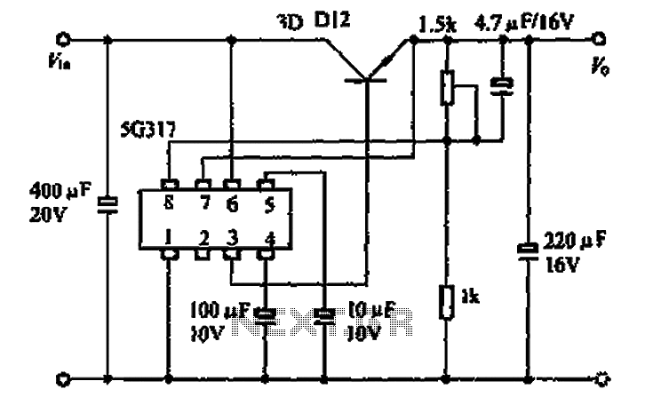
The 5G317 is an integrated voltage regulator circuit used in wiring applications for televisions. The maximum input voltage for the 5G317 should be less than 25V, while the output voltage ranges from 10V to 18V. The maximum output current,...
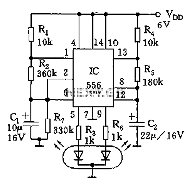
The circuit features a dual-core 556 timer IC and a light-emitting diode (LED) tube. The left half of the IC (556 1/2) comprises resistors R1, R2, capacitor C1, etc., generating a frequency of approximately 2 Hz in a multivibrator...
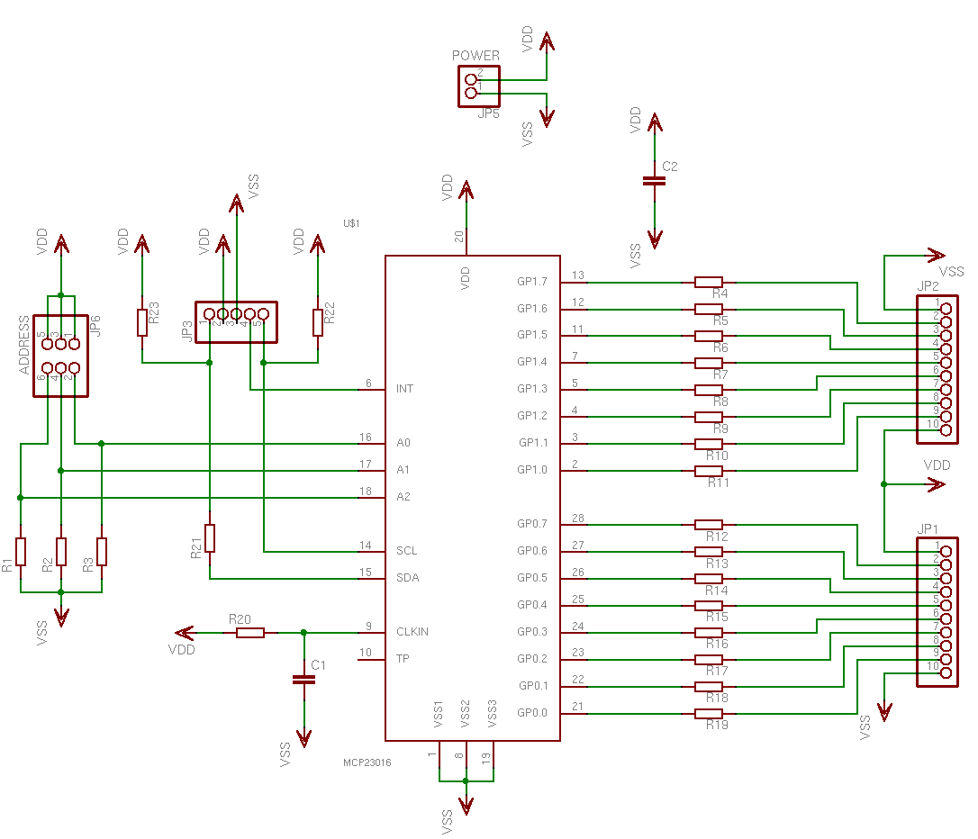
This is a simple, programmable, autonomous and extensible LED matrix with the possibility of being controlled by a computer using a RS232 connection. Its basic modules are the Controller Board, the I/O Port expander boards and the LED matrix...
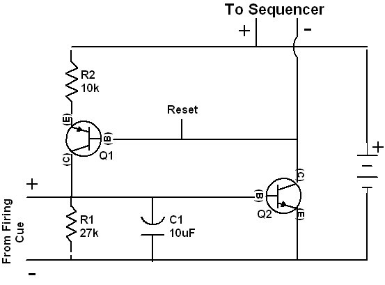
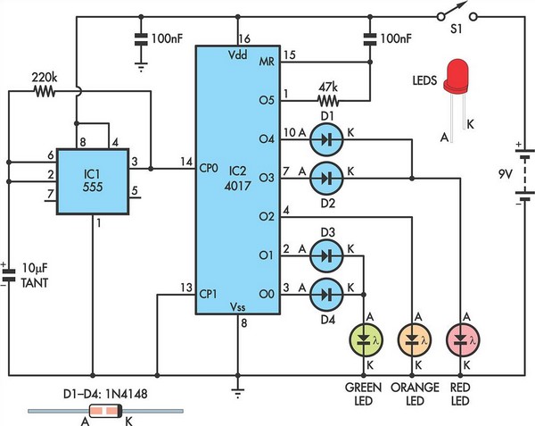
The 4017 integrated circuits are not initialized to a known state because the reset pins are not briefly forced high when the circuit is powered on. While the chips might typically power up in the normal reset condition, this...
Very often when enjoying music or watching TV at high audio level, we may not be able to hear a telephone ring and thus miss an important incoming phone call. To overcome this situation, the circuit presented here can...