
Sequencer circuit
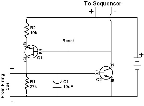
The 4017 decade counter is a versatile component commonly used in various digital circuits for counting applications. However, its proper configuration is critical for reliable operation. The initialization of the 4017 is vital; without ensuring that the reset pins are briefly forced high during power-up, the state of the outputs may become unpredictable. This lack of initialization can lead to erratic behavior in applications that depend on specific output states.
Shorting outputs Q2 through Q9 to the reset pin is a notable design flaw. In a typical application, each output should be independently controlled to ensure proper functioning. When Q2 is driven high, it inadvertently resets the counter, causing it to revert to its initial state, which can disrupt the intended counting sequence. This feedback loop can lead to unintended consequences, especially in designs requiring all outputs to function independently.
The race condition created by tying an output back to the reset pin can result in unreliable circuit operation. The timing of the reset pulse is contingent upon the propagation delay, which is typically not designed to handle such configurations. This can lead to scenarios where the reset does not occur as intended, further complicating the circuit's behavior.
The limitation of the 4017 in driving relays is another significant consideration. While it may appear to function in certain scenarios, relying on the 4017 to drive the positive side of a relay can lead to potential damage or failure of the IC. A dedicated driver circuit or a relay module with appropriate specifications should be employed to ensure reliable operation.
For applications requiring variable timing or complex logic, transitioning to microcontrollers offers a more robust solution. Microcontrollers provide the flexibility to implement various timing sequences, logic operations, and control mechanisms that can be adapted to meet specific project requirements. The availability of simple programming tools and community support makes them an attractive option for both novice and experienced designers.
Overall, careful consideration of circuit design and component selection is essential for achieving desired performance and reliability in electronic systems. Understanding the limitations and capabilities of components like the 4017, along with the advantages of microcontrollers, can significantly enhance the quality of electronic designs.First, the 4017`s aren`t initialized to a known state since the reset pins aren`t briefly forced high when the circuit powers on. The chips might usually power up in the normal reset condition, but that isn`t probably guaranteed by the IC manufacturer.
This is probably only a minor concern. Second, on the IC2 4017, outputs Q2 through Q9 are shorted together and tied to the reset pin. This is a major design flaw. This appears to be an attempt to modify the design of the lower schematic you provide. In that design, there are only 20 outputs used, and when IC2 toggles Q2 high, that high will reset IC2 back to Q0 being high. In your upper schematic, if you are really using all 10 banks of outputs on IC2, none of the outputs need to feed back to the reset pin.
Regardless, only certain types of logic can tolerate outputs being shorted together, and the 4017 isn`t one of them. Third, tying an output pin back to the asynchronous (instantaneous, not on a clock edge) reset pin creates what is called a race condition.
The width of the reset pulse will only be as long as the propogation delay from the reset pin to the output pin driving it. While this might work, there are a lot of circuit designers who wouldn`t do that. This is also probably only a minor concern. I agree with Cat that a 4017 can`t drive the positive side of a relay. Doing so might work for some reason (as the relay clicks in Janneman1`s video seems to prove), but unless you are using extremely sensitive relays that take little current to energize them, you are violating the output drive spec of the 4017.
I don`t know - maybe it works for very short relay pulses, or maybe the chip will put up with this for a while, but this is another major concern. Cat, the 555 schematic you pasted in isn`t the right one. That schematic is the monostable mode that generates one output pulse when the input is triggered. Janneman1 refers to figure 9b in the provided link, which is the correct astable or free running oscillator configuration.
Sorry I don`t have replacement schematics to offer. Cat is right - "think about how you shoot and build your system around that". There`s no one design that fits everyone. Frankly, my belief is that a system where delays and such need to be selectable are screaming for a microcontroller like a PIC or AVR. Sure, they might take some time to learn but once you have that out of the way, you`ll be amazed at how flexible your design can be without changing the hardware.
Also, programmers and software don`t have to be expensive or even purchased. Nearly all microcontrollers have simple programmers that can be built and software that can be downloaded, and all the microcontrollers I have looked at have forums like pyrouniverse that are invaluable for getting things working. Don`t just jump in and build something in a rush. Think about what you are trying to do, and spend time learning enough to understand things. Buy some parts. Play around. Figure out what works and what doesn`t. THEN start getting serious about a final design you`ll build for real. I`m sure everyone is glad you provided some feedback. I know very little about circuit design and would not have known there were problems outside the couple of thing I asked about.
Hopefully anytime anyone sees a major flaw in anyone`s design electronics or otherwise they will speak up. If you have time I would really like to understand more about this concern. Adding a resistor would not solve the problem How would one trigger the reset when they hit the end of a partial sequence and wanted to start over Cat, the 555 schematic you pasted in isn`t the right one.
That s 🔗 External reference
Related Circuits
To extend the measurement range of an available ADC (analog to digital converter), autoranging can be utilized. If implemented on multiplexed input, this... Autoranging is a technique employed in electronic measurement systems to automatically adjust the range of an analog-to-digital...
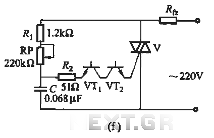
The introduction for a unidirectional thyristor trigger circuit is also applicable to the TRIAC. Various configurations are presented in Figure 16-28. Figures 16-28 (a) and (b) illustrate a direct trigger circuit; Figure 16-28 (c) depicts a dual diode trigger...
The following circuit illustrates a Plant Moisture Meter Circuit Diagram. This circuit is based on the LM741 integrated circuit (IC). Features include a meter that indicates moisture levels. The Plant Moisture Meter Circuit utilizes the LM741 operational amplifier to measure...
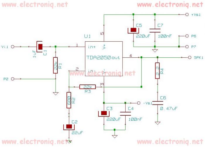
The TDA2050 integrated circuit can be used to design a simple high-fidelity audio power amplifier, intended for use as a Class AB audio amplifier. Due to its high power capabilities, the TDA2050 audio power amplifier can deliver up to...
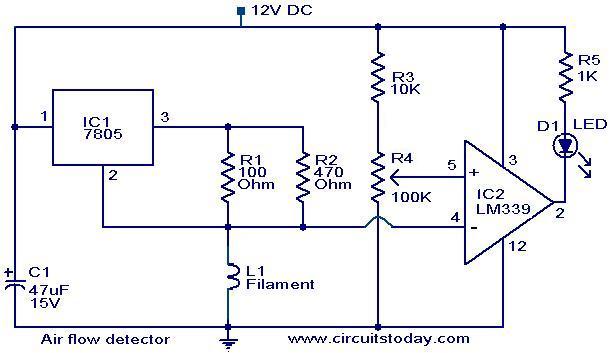
The filament of an incandescent bulb serves as the sensing component of the circuit. When there is no airflow, the resistance of the filament is low. In contrast, when airflow is present, the resistance decreases because the moving air...
Long-distance infrared transmitter circuit diagram. This simple circuit offers a considerable range by utilizing three infrared transmitting LEDs (IR1 through IR3) in series to enhance the radiated power. To further improve directivity and power density, the IR LEDs can...
Warning: include(partials/cookie-banner.php): Failed to open stream: Permission denied in /var/www/html/nextgr/view-circuit.php on line 713
Warning: include(): Failed opening 'partials/cookie-banner.php' for inclusion (include_path='.:/usr/share/php') in /var/www/html/nextgr/view-circuit.php on line 713