
Bass-treble tone control circuits
The low distortion bass and treble control circuit is designed to enhance the audio quality of an amplifier by allowing precise adjustments to the low and high-frequency response. This circuit typically utilizes operational amplifiers (op-amps) configured in a tone control arrangement, which can effectively modify the amplitude of bass and treble frequencies while minimizing distortion.
In a typical implementation, the circuit may include a dual op-amp configuration where one op-amp is dedicated to bass control and the other to treble control. The frequency response can be adjusted by varying the feedback and gain settings of each op-amp. Passive components such as resistors and capacitors are strategically placed to define the cutoff frequencies for the bass and treble bands.
For instance, the bass control section can be designed with a low-pass filter configuration, where a potentiometer allows the user to increase or decrease the gain of frequencies below a certain threshold, typically around 100 Hz. Conversely, the treble control section employs a high-pass filter to boost or attenuate frequencies above a specified cutoff, often around 3 kHz.
The circuit diagram illustrates the connections between the op-amps, power supply, input, and output stages. Power supply decoupling capacitors are also included to ensure stable operation and reduce noise. Additionally, a bypass capacitor may be employed to filter out high-frequency noise from the power supply lines, further enhancing the performance of the circuit.
Overall, this low distortion bass and treble control circuit is an essential component for audiophiles and audio engineers looking to customize their audio experience by achieving a balanced sound profile tailored to individual preferences.Low distortion bass and treble control for amplifier. Circuit diagram. Electronics projectt.. 🔗 External reference
Related Circuits
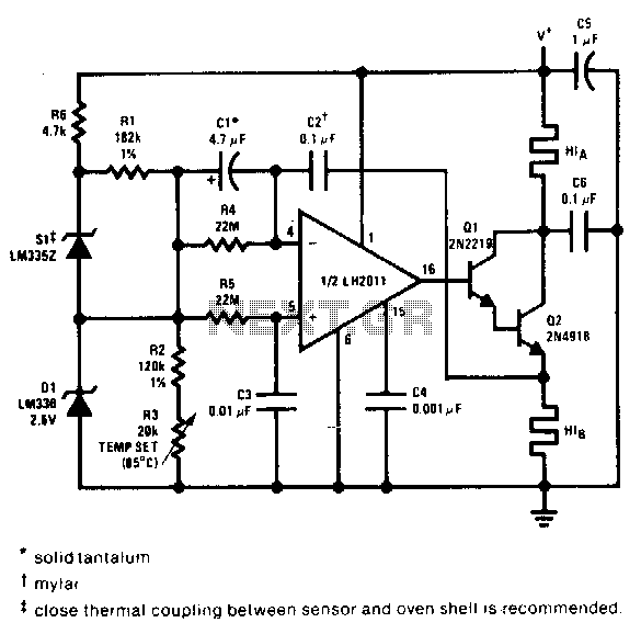
This proportional control crystal oven heater utilizes lead/lag compensation to achieve rapid setting. The time constant can be adjusted using resistor R4 and the compensating resistor R5. It is advisable to use a regulated supply for Q2 if it...
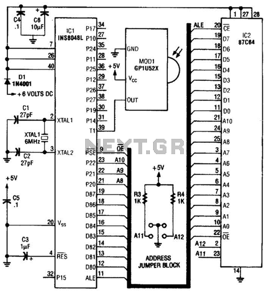
This circuit is based on the Sharp GP1U52X infrared module and the 1NS8048L microprocessor. The GP1U52X is a hybrid integrated circuit and infrared detector that provides a strong, clean signal for subsequent filtering and demodulation. The circuit utilizes the Sharp...
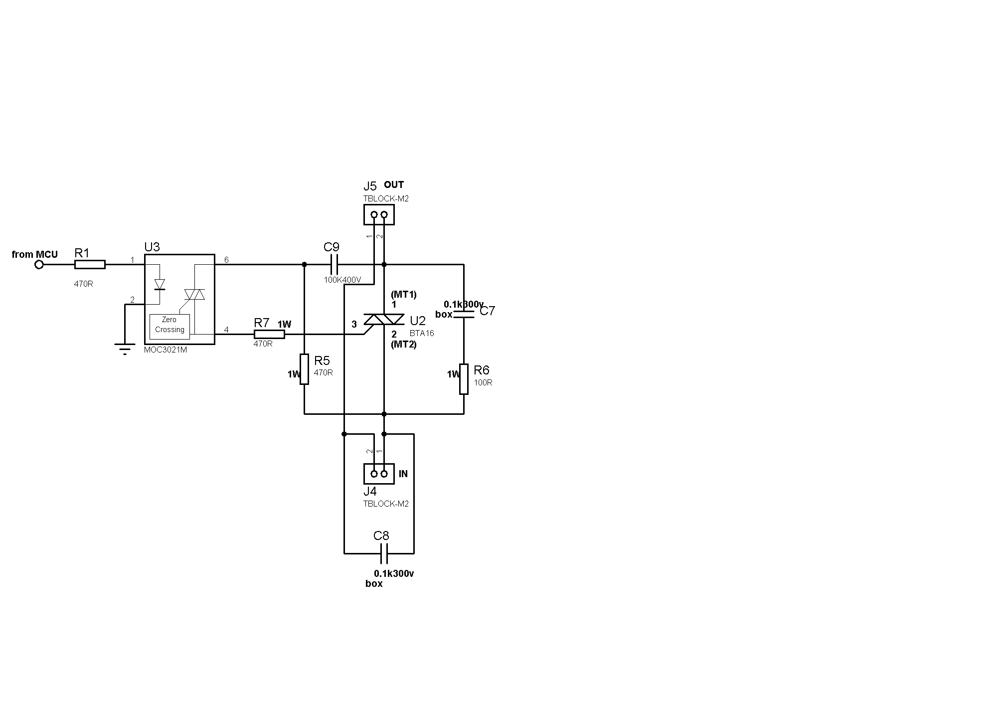
Sufficient snubbering appears to be present around the TRIAC, which should mitigate DV/DT-based switching, preventing the TRIAC from inadvertently turning on due to noise on the gate lead. The issue likely resides on the microcontroller side. When the microcontroller...
The ATA5423, ATA5425, ATA5428, and ATA5429 are highly integrated UHF ASK/FSK multi-channel half-duplex transceivers characterized by low power consumption. These devices are housed in a compact 7 x 7 mm QFN48 package. The receiving section features a fully integrated...
The ICL7665S Super CMOS Micropower Over/Under Voltage Detector features two low-power, individually programmable voltage detectors integrated on a single CMOS chip. It typically requires 3 µA for operation and is designed for battery-operated systems and instruments that need high...
The photocell photoelectric tracking circuit is configured with two identical photoelectric cells that serve as light-receiving devices. When the incident light intensity is equal, the system is able to track in a predetermined manner. If there is a slight...
Warning: include(partials/cookie-banner.php): Failed to open stream: Permission denied in /var/www/html/nextgr/view-circuit.php on line 713
Warning: include(): Failed opening 'partials/cookie-banner.php' for inclusion (include_path='.:/usr/share/php') in /var/www/html/nextgr/view-circuit.php on line 713