
speedcontroller TRIAC switching problem
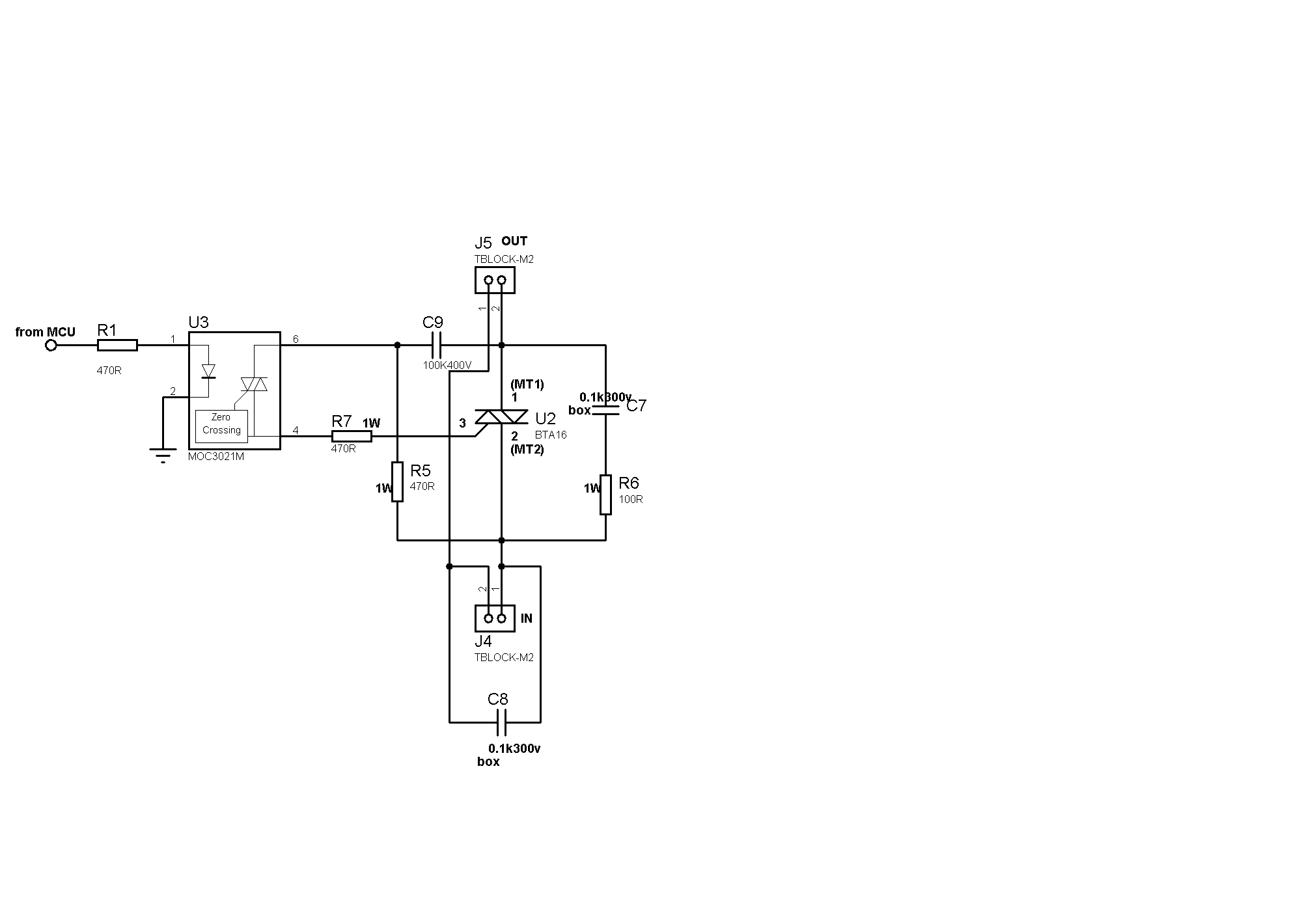
The circuit in question involves the use of a TRIAC for switching applications, typically in AC loads. The presence of snubbering components is essential to protect the TRIAC from voltage transients that could cause unintended triggering. The microcontroller plays a crucial role in controlling the TRIAC through an optocoupler, which provides electrical isolation between the high-voltage AC side and the low-voltage control side.
In this configuration, the optocoupler is utilized to isolate the microcontroller from the AC load. The redesign of the microcontroller circuit is necessary to ensure that the optocoupler operates reliably. The optocoupler's LED should be connected such that it receives a clear HIGH signal when the microcontroller intends to turn on the TRIAC. By connecting the anode of the optocoupler LED to the positive voltage supply and the cathode to the microcontroller pin via resistor R1, the microcontroller can actively control the LED state.
The choice of R1 is critical; it should be selected to limit the current to the optocoupler's LED within its specified range while ensuring that a sufficient voltage drop occurs across it when the microcontroller pin is LOW. This design modification eliminates the risk of the LED being partially illuminated due to weak pull-up currents during the reset state of the microcontroller.
Additionally, the incorporation of an external pull-up resistor on the microcontroller pin is advisable for enhanced reliability in maintaining the optocoupler in an OFF state when not actively driven LOW. This measure is particularly important when dealing with line voltages, where unintended triggering could pose safety hazards.
Finally, analyzing the specifications of the TRIAC is essential, especially if it is classified as a sensitive-gate TRIAC. In environments with significant electrical noise, the characteristics of the TRIAC may necessitate further protective measures, such as improved snubbering circuits, to ensure stable operation without false triggering. The overall design should prioritize both functionality and safety in controlling AC loads through microcontroller interfacing.You already appear to have sufficient snubberring around the TRIAC which should eliminate DV/DT based switching (the TRIAC turning itself on due to noise on the gate lead) which I believe that your issue is on the micro side of things. I think your issue is as follows. When the micro is in reset, all of its pins are inputs. This isn`t quite the same thing as having the left side of R1 disconnected since the micro also probably has internal pullups. These pullups are too weak to drive the opto LED strongly, but I bet if you put a meter across R1 you will see maybe a few dozen to a hundred microvolts.
That might be enough to trigger that opto. I would rework the micro side of your circuit so that the anode of the optocoupler LED goes to +V and the cathode goes to your micro through R1; your micro will then have to drive the output LOW to turn on the TRIAC, but it will eliminate that brief moment where the micro comes out of reset and the pin is an input and drives the LED weakly. I would also add an external pull-up resistor just because you`re working with line voltage and I like the assurance of a stronger pull-up resistor to make sure the opto stays off.
I would also investigate the larger TRIAC to see what exactly its switching characteristics are. If it`s a sensitive-gate TRIAC and you have a noisy environment you may need to take a closer look at your snubberring. 🔗 External reference
Related Circuits
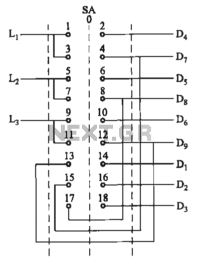
The motor switch control circuit depicted in the figure provides two speed settings for counter-steering, allowing for operation at two speeds in opposite directions. The motor switch control circuit is designed to facilitate the operation of a motor at two...

The self-designed amplifier circuit described is completely symmetrical and complementary, effectively utilizing the advantages of complementary NPN and PNP transistors to achieve a high degree of stability. The circuit features good symmetry in the push-pull amplification state, allowing for...

Two or more signals can be switched and/or mixed without annoying clicks by using FETs and a low input-impedance op amp circuit. The circuit design utilizes Field Effect Transistors (FETs) to facilitate the switching and mixing of multiple signals while...

This power supply utilizes an SGS-Thomson UC3842 integrated circuit in an off-line flyback regulator configuration, delivering +5 V at 4 A and ±12 V at 300 mA. This design allows for the use of a compact high-frequency (50 kHz)...
A switching power supply that has an output voltage significantly lower than its input voltage exhibits a unique characteristic: the current drawn from the supply is less than the output current. However, the input power (UI) is, naturally, greater...

MSP430 microcontroller and I2C-compatible slave peripheral device. Temperature measurement tasks can be accomplished in a variety of ways. The MSP430 microcontroller is a low-power, 16-bit device widely used in embedded systems, particularly for applications requiring efficient power management and precise...
Warning: include(partials/cookie-banner.php): Failed to open stream: Permission denied in /var/www/html/nextgr/view-circuit.php on line 713
Warning: include(): Failed opening 'partials/cookie-banner.php' for inclusion (include_path='.:/usr/share/php') in /var/www/html/nextgr/view-circuit.php on line 713