
battery amp
The first complication arises in defining cathode voltage. To generate heat, a voltage is applied across a resistance, causing one end of the filament to be at a higher voltage than the other. When the filament also serves as the cathode, its voltage will vary along its length, leading to different cathode voltages at various points. Tube manufacturers simplify this by referencing all voltages in the datasheet to the negative side of the cathode. For example, with a 1.5-volt battery connected to the filament, the cathode voltage is defined as the voltage at the negative terminal of the battery. All datasheet curves are referenced to this point. If the datasheet indicates a grid voltage of -5 volts, the actual grid-to-cathode voltage ranges from -5 volts (between the grid and the negative terminal) to -6.5 volts (between the grid and the positive terminal).
In conventional guitar amplifiers, a single heater supply is commonly connected to all filaments in parallel. However, this approach is not feasible in battery amplifiers. For instance, cathode followers, concertina phase splitters, and long-tailed-pair phase inverters have cathodes that float at voltages significantly above ground. Traditional single-ended guitar amplifiers employ cathode-biased preamps and power amplifiers, which position the cathodes at positive potentials corresponding to the desired DC grid bias voltages. Connecting heaters in parallel necessitates equalizing cathode voltages. Consequently, designers must account for filament heating in relation to cathode DC voltage. Notably, prominent designers like Leo Fender and Jim Marshall did not encounter this challenge in their production guitar amplifiers.
Even when all cathodes are grounded, utilizing a single battery for the entire circuit is often impractical or inefficient. Typically, three batteries are required, each named based on historical usage when radios operated on batteries and AC power supplies for consumer electronics were not yet available. In a standard radio from 1925, the "A" battery provided filament heat, which was the primary power consumption source. This battery was large, producing low voltage and high current, and was often a lead-acid type requiring weekly recharging by local mechanics. The "C" battery established the DC grid voltage and did not necessitate an on-off switch, as grid current was minimal during operation and nonexistent when heaters were off. Consequently, the C battery could remain continuously connected, often collecting dust and eventually failing due to age.
As battery voltage and current decrease over time, voltage gain typically diminishes, and DC voltages can fluctuate as the battery ages. Additionally, operating close to cutoff with fresh batteries may lead to signal clipping as the batteries deplete. Therefore, the amplifier design must accommodate the full range of voltage variations experienced over the batteries' lifespan.
In summary, battery amplifier design involves unique considerations such as the integration of heating and cathode functions, the management of varying cathode voltages, and the implications of using multiple batteries to ensure consistent performance throughout the operational life of the amplifier.Traditional guitar amp tubes like the venerable 12AX7 use indirectly-heated cathodes. The heat-producing filament is electrically isolated from the cathode that provides signal-producing electrons. This simplifies the design considerably, because the cathode can be set to a voltage that is completely independent of the heater supply.
Battery tubes , on the other hand, use directly-heated cathodes to preserve battery life. By creating its own heat the cathode of a 1T4 battery pentode, for example, consumes almost 30-times less energy than in a 12AX7. In battery tubes the cathode and heater are the same. This puts significant constraints on the designer, presenting additional challenges not normally found in a guitar amplifier.
In this article we will outline some of the basic principles of battery amp design. The first complication involves the definition of cathode voltage. To create heat we apply a voltage across a resistance. Thus one end of the filament is at a higher voltage than the other end. If the filament is also acting as the cathode, then its voltage gradually varies from one end to the other. So there are different cathode voltages measured all along its surface. This sounds complicated, but tube manufacturers simplify our calculations by referencing all voltages in the data sheet to the minus side of the cathode.
When a 1. 5-volt battery is placed across the filament to create heat, the cathode voltage is defined as the voltage at the negative end of the battery. All the curves in a data sheet are referenced to this point. If the data sheet refers to a grid voltage of -5 volts, for example, then the actual grid-to-cathode voltage varies from -5 volts (measured between the grid and the negative end of the battery) to -6.
5 volts (measured between the grid and the positive end). In a typical guitar amplifier a single heater supply is routed to all the filaments in parallel. This is not always possible in a battery amp. Cathode followers, concertina phase splitters, and long-tailed-pair phase inverters, for example, have cathodes that float at a voltage much higher than ground. Traditional, single-ended guitar amps have cathode-biased preamps and power amps, which puts the cathodes at positive potentials equal to the desired DC grid bias voltages.
You can`t connect heaters in parallel without making the cathode voltages the same. Bottom line: the designer has to consider filament heating in the context of cathode DC voltage. Leo Fender and Jim Marshall never faced this challenge, at least in production guitar amps. Even if all the cathodes are held at ground potential it is difficult, or at least inefficient, to use a single battery for everything. Generally 3 batteries are required, each having a name derived almost a century ago, when radios operated off batteries and an AC power supply for consumer electronics was still way into the future.
In a typical radio built in 1925, the "A" battery supplied filament heat. This is where most power consumption took place. The battery was physically large and created low voltage and high current. It was usually a lead-acid battery charged every week by the automobile mechanic down the street. Finally the "C" battery set the DC grid voltage. There was never any need for an on-off switch for this battery either, because grid current was extremely low while operating and non-existent when the heaters were turned off. Thus the C battery was also left continuously connected. Through the years it collected dust and cobwebs and eventually died of old age. Voltage gain generally decreases as voltages and currents decrease, and DC voltages vary as the battery ages.
Worse things can also happen. Placing the DC operating point close to cutoff using fresh batteries, for example, can create signal clipping as the batteries wear down. The amp needs to be designed for the full range of voltages experienced over the lifetimes of 🔗 External reference
Related Circuits

This is a simple yet effective charger for lead-acid batteries. It utilizes a 12-volt car bulb as both a current regulator and a charge status indicator. The described circuit is an innovative approach to charging lead-acid batteries. It employs...
This circuit is permanently plugged into a mains socket and NI-CD batteries are trickle-charged. When a power outage occurs, the lamp automatically illuminates. Instead of illuminating a lamp, an alarm sounder can be chosen. When power supply is restored,...
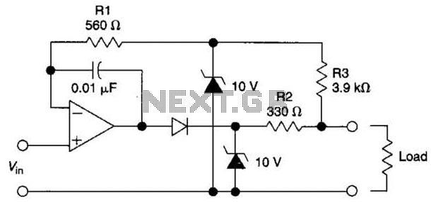
The circuit is designed to drive an external load. A fault condition in the external load circuit could feed excessive current or voltage back into the line drive circuit. If excessive voltage appears from the load, the two zener...
This is a rather unusual QRP Power Amplifier design, with a wide frequency response; within three dB's from 300KHz to 30MHz. Overall gain is in the region of 16dB and the final output power may be well over four...
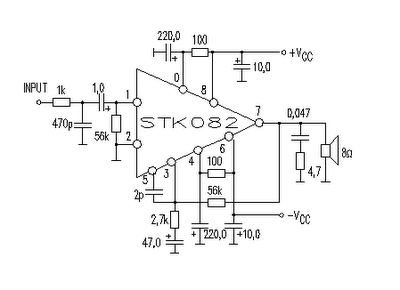
This amplifier circuit is suitable for home power audio devices. The STK082 amplifier specifications suggest that it can operate with supply voltages of up to ±43V. However, it is advisable to use no more than ±25V for 8-ohm loads,...
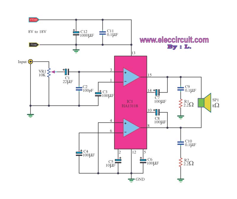
The amplifier circuit utilizes the HA13118 IC, a Hitachi component designed to deliver 18 watts of output power. This integrated circuit operates as a Class AB amplifier. The HA13118 IC is a versatile audio amplifier designed for high-fidelity applications, providing...