
35w audio amplifier circuit by stk082
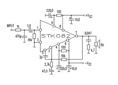
The STK082 amplifier is a high-performance audio amplifier designed for home audio applications, capable of delivering significant power output while maintaining sound quality. The circuit typically incorporates a complementary push-pull configuration, which enhances efficiency and reduces distortion.
The recommended supply voltage range of ±25V to ±30V is critical for optimal performance, especially when driving 8-ohm speakers. Exceeding the voltage rating can lead to thermal issues or potential damage to the amplifier, particularly if insufficient heatsinking is employed. Adequate heatsinking is essential to dissipate heat generated during operation, ensuring the amplifier remains within safe temperature limits.
The circuit design includes input and feedback networks to stabilize gain and reduce noise, contributing to the overall audio fidelity. Bypass capacitors are also used to filter out power supply noise, enhancing the performance of the amplifier in real-world applications.
In terms of component selection, high-quality resistors and capacitors are recommended to minimize signal degradation. The output stage may include output transistors rated for high current to ensure that the amplifier can drive speakers effectively without clipping.
Overall, the STK082 amplifier circuit is a robust solution for home audio applications, providing users with a reliable and high-quality audio experience when properly implemented within the specified voltage and thermal guidelines.This amplifier circuit is suitable for home power audio devices. The STK082 amplifier specifications might lead you to believe that it can use supply voltages of up to ±43V. but I don`t recommend anything greater than ±25V if 8 ohm loads are expected, although ±30V will be fine if you can provide good heatsinking.
🔗 External reference
Related Circuits
The electronic switch consists of the CK-4 type magnetic control switch and the components VT1, R1, and R2. When the bathroom door is closed, the permanent magnet ZT and the reed switch GA come into proximity, which separates the...
As shown in the figure, the 555 timer, resistors R1, RP1, and capacitor C1 form a controlled audio oscillator. The frequency of the oscillator is given by the formula f = 1.44 / ((R1 + 2 * RP1) *...
A 555 timer operating in astable mode generates driving pulses, while two 4518 dual BCD (binary coded decimal) counters provide square waves. A TL081 operational amplifier functions as an output buffer-amplifier. Potentiometers R1 and R2 are utilized to control...
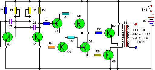
This is a simple and cost-effective inverter designed for small soldering irons (25W, 35W, etc.) to be used in the absence of mains supply. The circuit employs eight transistors along with a few resistors and capacitors. Transistors Q1 and...
The circuits on this page are for an Infrared Proximity Detector using the Vishay Electronics TSOP4830, which is an IR Receiver Module designed for remote control systems. The TSOP4830 functions as a sensitive infrared detector that operates without requiring...
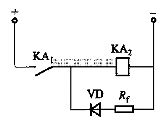
The circuit depicted in Figure 6-24 includes a relay coil with both ends connected in parallel to a resistor (Rf) or an auxiliary diode (VD). This configuration is intended to enhance power after a short circuit occurs in the...