
Battery Test Circuit Circuit
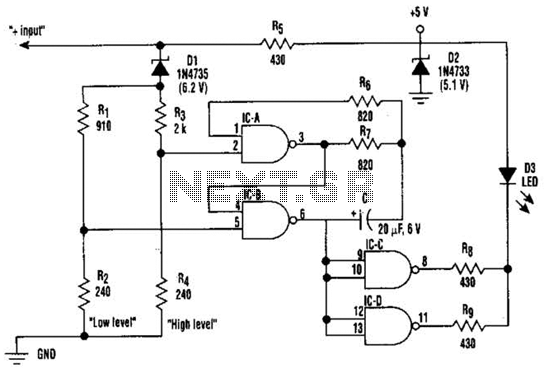
The circuit employs a voltage comparator to monitor the input voltage and determine its level. The reference voltages for low and high thresholds can be set using a voltage divider network, which typically consists of resistors. For the low voltage threshold (11 V), the circuit can be designed using an operational amplifier configured as a comparator. When the input voltage drops below this threshold, the output of the comparator switches, turning the LED on steadily to indicate a low voltage condition.
In the normal voltage range (11 to 15 V), the comparator output remains low, keeping the LED off. To detect the high voltage condition (greater than 15 V), a second comparator can be implemented. This comparator would be configured to activate when the input voltage exceeds the high threshold. Upon activation, a timer circuit, such as a 555 timer in astable mode, can be integrated to cause the LED to blink at a frequency of 1 Hz, providing a visual indication of the high voltage status.
The circuit's design ensures that it can handle a range of input voltages while providing clear visual feedback through the LED. Additionally, the use of appropriate resistors and capacitors will stabilize the circuit operation and prevent false triggering due to transient voltage spikes. This voltage level indicator circuit serves as a critical tool in monitoring electrical systems, ensuring they operate within safe voltage ranges, and alerting users to potential issues before they escalate. Using this circuit, tiiree levels of voltage can be displayednormal (11 to 15 V), liigh (>15 V), and low (11 V). When the voltage is low, the LED glows steadily. In the normal range, the LED is off. When the voltage is high, the LED blinks at a 1-Hz rate. This circuit is useful for assuring proper electrical system operation. 🔗 External reference
Related Circuits
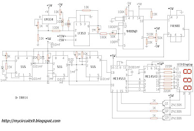
This circuit consists of a temperature sensor, amplifier, voltage-to-frequency (V/F) converter, a three-digit binary coded decimal (BCD) counter, a time base, and seven-segment LED displays. In addition to the 9400 V/F converter, other integrated circuits (ICs) required for this...
Logic-1 and logic-0 represent the states of digital signals, where logic-1 corresponds to a high voltage close to Vcc, and logic-0 corresponds to a voltage near neutral or ground. Logic-0 cannot be transformed into logic-1, while logic-1 can revert...
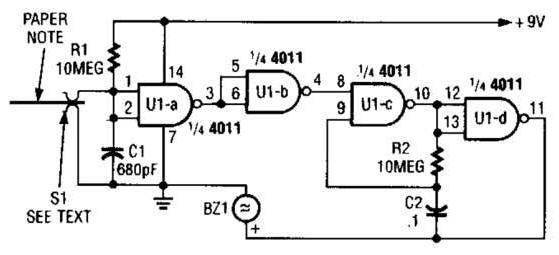
This device prevents paper notes and memos from being overlooked. A paper note placed between two fingers made of a conducting material (metal or conductive plastic) breaks the circuit, allowing pair 1 of Ul-a to go high. The goal...
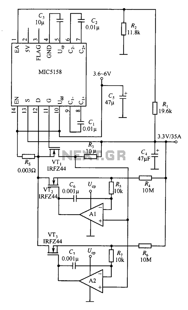
The MIC5158 is designed to manage tasks by controlling multiple external N-channel MOSFETs in parallel, which enables high current or high power output for a linear regulator circuit. This is illustrated in the accompanying figure. The operational amplifier circuit...
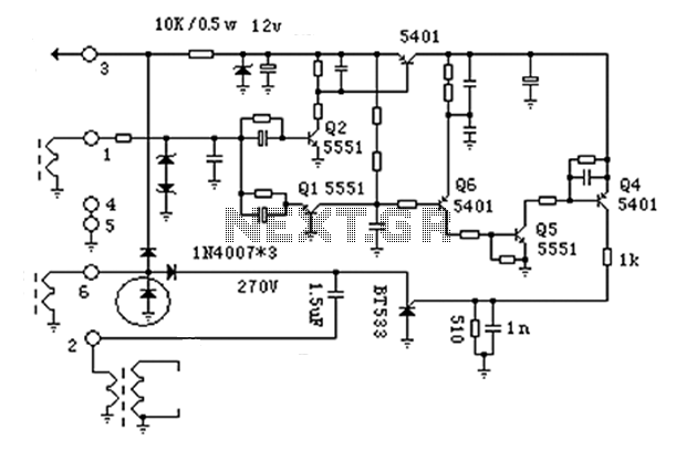
The anatomy of two ignition experiments revealed a common issue, specifically that both ends of the ignition coil are equipped with a diode. This design choice by manufacturers has implications for performance. The ignition coil generates a negative half-cycle...
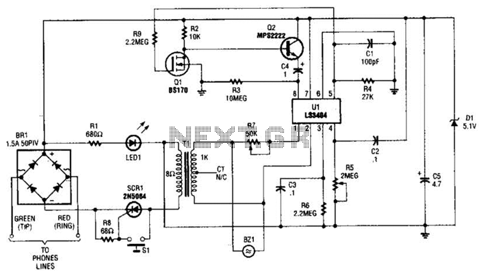
The LS3404 melody chip is activated when the hold switch (SI) is pressed, causing SCR1 to conduct and maintain the telephone line through Tl, Rl, and LED1. The voltage across Rl and LED1 is utilized to power the melody...