
Music On Hold Box Circuit
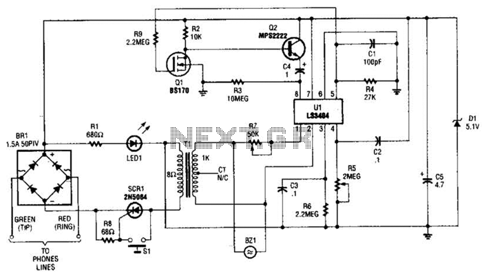
The LS3404 melody chip is a specialized integrated circuit designed to generate musical tones. Upon pressing the hold switch (SI), an electrical signal is sent to the gate of the silicon-controlled rectifier (SCR1), which then enters the conductive state. This action effectively connects the telephone line to the circuit, allowing the melody chip to function.
Resistor Rl and LED1 are connected in series, forming a voltage divider that provides the necessary operating voltage to the melody chip. The LED1 serves a dual purpose; it not only indicates that the hold function is active but also contributes to the voltage drop across Rl. This voltage is critical for the proper functioning of the LS3404, ensuring that it receives sufficient power to operate.
Transistors Q1 and Q2 are configured to create a restart circuit that maintains the melody chip's operation. When the melody chip is activated, Q1 turns on, allowing current to flow through Q2, which keeps the circuit in a stable state. This configuration prevents the melody chip from shutting down during the hold period, ensuring continuous sound output. The restart circuit is essential for applications where the hold function may be activated for extended durations, as it guarantees that the melody continues to play without interruption.
The overall design allows for a seamless user experience during the hold operation, combining visual feedback through LED1 and auditory feedback through the melody chip, while ensuring reliability through the restart circuit. This arrangement is particularly useful in telephone systems where maintaining communication aesthetics is important. Ul, an LS3404 melody chip is activated when hold SI is pressed, which causes SCR1 to conduct and hold the telephone line via Tl, Rl, and LED1. The voltage across Rl and LED1 is used to activate the melody chip. Ql and Q2 form a restart circuit to keep the melody chip going during hold. 🔗 External reference
Related Circuits
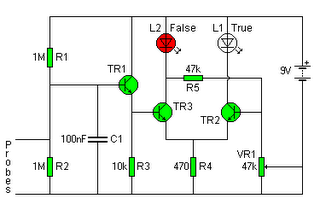
The following circuit illustrates a Lie Detector Circuit Diagram. Features include a capacitor that eliminates the 50Hz induced mains hum present in the circuit. The Lie Detector Circuit operates on the principle of measuring physiological responses, typically galvanic skin response...
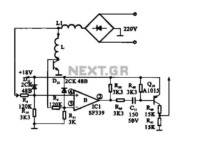
The cookers pot quality detection circuit is designed to assess the quality of cooking pots. The testing process utilizes a disc lesion-induced voltage (EMF) to determine the pot's quality. The cookers pot quality detection circuit employs a method based on...
The circuit consists of an infrared transmitter-receiver pair that uses infrared beam transmission to switch the toy car on or off. It can be modified to allow the toy car to turn left or right. To operate the toy...
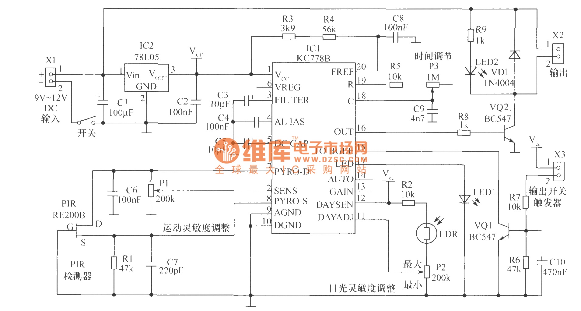
The core component of the motion detection circuit is the motion detection chip IC1 (KC778B). The signal frequency from the PIR sensor is low, ranging from 0.1Hz to 10Hz, while the bandwidth is quite broad, which the chip will...
The following circuit illustrates a Bass and Treble Controller Circuit. This circuit is constructed based on the classic Baxandall tone control circuitry. The Bass and Treble Controller Circuit is designed to adjust the low and high-frequency response of audio signals,...
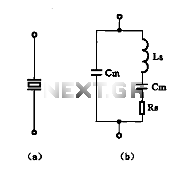
The crystal equivalent RLC circuit is illustrated. The RLC circuit can operate in either a series resonant or parallel resonant configuration. The crystal equivalent RLC circuit is a fundamental electronic circuit that models the behavior of a crystal oscillator. This...
Warning: include(partials/cookie-banner.php): Failed to open stream: Permission denied in /var/www/html/nextgr/view-circuit.php on line 713
Warning: include(): Failed opening 'partials/cookie-banner.php' for inclusion (include_path='.:/usr/share/php') in /var/www/html/nextgr/view-circuit.php on line 713