
Beeper Using 1C 555

The beeper circuit described employs two 555 timer ICs arranged in astable configurations to produce distinct frequencies that interact to create a beeping sound. The first 555 timer (IC1) generates a low-frequency square wave at approximately 1 Hz, which serves as a control signal for the second timer (IC2). The second timer operates at a higher frequency of around 1 kHz, producing a continuous tone. The interaction between the two frequencies results in an audible beep, as the 1 Hz square wave from IC1 resets IC2, effectively interrupting its output.
The output from IC1 at pin 3 is crucial as it directly influences the operation of IC2. When IC1 outputs a high signal, it resets IC2, silencing the 1 kHz tone momentarily. This creates a distinct beeping pattern, where the frequency of the beeps corresponds to the output frequency of IC1. Capacitor C4 serves an essential role in the circuit by blocking any DC signals that could interfere with the operation of the timers, ensuring that only the intended AC signals affect the output.
For applications involving logic ICs, such as CMOS and TTL, adjustments to the circuit configuration are necessary. Specifically, the reset pin (pin 4) of IC2 must be connected to the output of the logic element that will control the beeper. This modification allows the logic level to dictate the activation of the beeper; a high logic level at pin 4 will turn the beeper on, while a low logic level will turn it off. This flexibility makes the circuit adaptable for various control schemes, enhancing its utility in electronic projects requiring auditory alerts or signals.
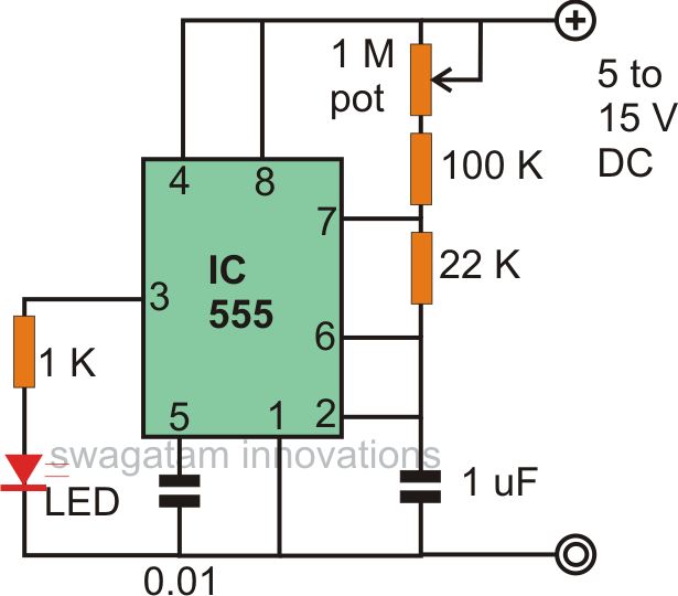
Overall, this beeper circuit is a versatile solution for generating audible alerts, with straightforward modifications that enable integration with different control logic systems.Here is a `beeper` circuit employing two 555 ICs. It can be used in various circuits (having supply voltage of 5 to-15V DC) that require an alarm or a `beeping` signal. IC1 is connected in astable mode in the circuit in such a way that squarewave output at about 1 Hz is obtained.
lC2is also connected in astable mode, but it gives an output with ab out 1 kHz frequency. The output of IC1 (pin 3) is connected to `Reset` terminal (pin 4) of IC2. So, the continuous I kHz tone of IC2 is interrupted by the I Hz signal from IC1, producing a`beep-ing` sound. Capacitor C4 is used to restrict DC signals. The circuit operates satisfactorily when it is to be activated by a relay or a mechanical switch, but when it is to be operated by logic ICs, such as CMOS or TTL ICs, a bit of modification is required.
Instead of connecting pin 4 of ICI to Vcc, it should be connected to the output of the logic element through which it is to be activated. A logic`I`at pin4 will activate the beeper and logic `0` will turn it off. Rest of the circuit would remain the same. 🔗 External reference
Related Circuits

Introduction The design of off-line constant voltage, constant current (CVCC) power supplies using the NCP1014 for devices such as cell phones, hand tools, and similar battery chargers can present various challenges when low cost and circuit simplicity are required...
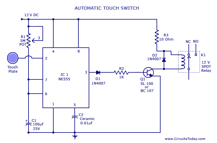
A touch switch circuit schematic utilizing a 555 integrated circuit (IC). When the touch plate is activated, a relay is switched ON for a predetermined duration, which can also be adjusted. The touch switch circuit employs a 555 timer IC...
Due to their speed, accuracy, effectiveness, and cost-efficiency, infrared (IR) digital thermometers have supplanted traditional mercury thermometers. An ear digital thermometer utilizes a thermopile sensor to measure the infrared heat emitted by the eardrum, which correlates with the temperature...
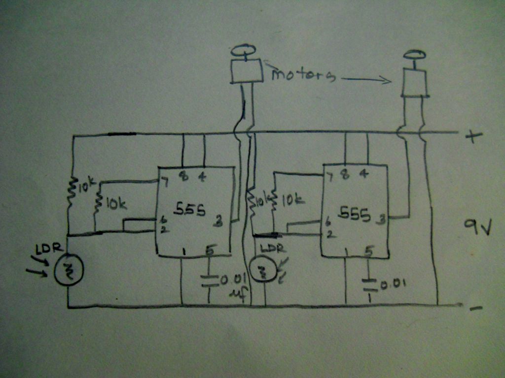
The schematic diagram of this robot is straightforward to comprehend. It is based on modifications made to a circuit from one of the reference books. The schematic for the robot features a basic structure that integrates various electronic components to...
The astable multivibrator mode is the most basic operational mode of the IC 555. In this mode, it functions as a free-running oscillator. When the oscillator rate is sufficiently reduced, it can be used to drive LED lights. The...

A simple touch dimmer circuit diagram using the TT6061 IC, which is a touch control integrated circuit used for light dimmer circuits and lamp dimmer circuits. The touch dimmer circuit utilizing the TT6061 IC is designed to provide a user-friendly...