
BH1417 Stereo FM Transmitter
The FM Micromitter is designed for simplicity and ease of use, making it suitable for both amateur and professional applications. The compact design allows for versatile placement in various environments, including home audio systems, automotive applications, and outdoor settings. The use of a crystal-locked oscillator ensures consistent performance, which is critical for maintaining audio quality over the transmission range. The selected frequency options provide flexibility for users, allowing them to choose less crowded frequencies to minimize interference.
The internal architecture of the BH1417F IC facilitates high-quality audio transmission, with dedicated processing for each audio channel, ensuring that stereo separation is maintained. The pre-emphasis feature is particularly beneficial for enhancing the clarity of music and speech, making the Micromitter an excellent choice for broadcasting audio content in various scenarios. Overall, the FM Stereo Micromitter represents a significant advancement in FM transmission technology, offering improved performance and user-friendly features compared to its predecessors.This new stereo FM Micromitter is capable of broadcasting good quality signals over a range of about 20 metres. It`s ideal for broadcasting music from a CD player or from any other source so that it can be picked up in another location.
For example, if you don`t have a CD player in you car, you can use the Micromitter to broadcast signals from a p ortable CD player to your car`s radio. Alternatively, you might want to use the Micromitter to broadcast signals from your lounge-room CD player to an FM receiver located in another part of the house or by the pool. Because it`s based on a single IC, this unit is a snack to build and fits easily into a small plastic utility box.
It broadcasts on the FM band (ie, 88-108MHz) so that its signal can be received on any standard FM tuner or portable radio. However, unlike previous FM transmitters published in SILICON CHIP, this new design is not continuously variable over the FM broadcast band.
Instead, a 4-way DIP switch is used to select one of 14 preset frequencies. These are available in two ranges covering from 87. 7-88. 9MHz and 106. 7-107. 9MHz in 0. 2MHz steps. We first published an FM stereo transmitter in SILICON CHIP in October 1988 and followed this up with a new version in April 2001. Dubbed the Minimitter, these earlier versions were based on the popular Rohm BA1404 IC which is not being produced any more.
On both these earlier units, the alignment procedure requires careful adjustment of the ferrite tuning slugs within two coils (an oscillator coil and a filter coil), so that the RF output matched the frequency selected on the FM receiver. However, some constructors had difficulty with this because the adjustment was quite sensitive. In particular, if you had a digital (ie, synthesised) FM receiver, you had to set the receiver to a particular frequency and then carefully tune the transmitter frequency "through" it.
In addition, there was some interaction between the oscillator and filter coil adjustments and this confused some people. That problem doesn`t exist on this new design, since there is no frequency alignment procedure. Instead, all you have to do is set the transmitter frequency using the 4-way DIP switch and then dial-up the programmed frequency on your FM tuner.
The new FM Stereo Micromitter is now crystal-locked which means that the unit does not drift off frequency over time. In addition, the distortion, stereo separation, signal-to-noise ratio and stereo locking are much improved on this new unit compared to the earlier designs.
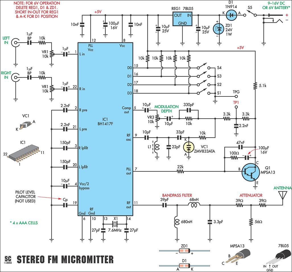
The specifications panel has further details. Fig. 2: this frequency versus output level plot shows the composite level (pin 5). The 50ms pre-emphasis at around 3kHz causes the rise in response, while the 15kHz low pass roll off produces the fall in response above 10kHz. At the heart of the new design is the BH1417F FM stereo transmitter IC made by the Rhom Corporation. As already mentioned, it replaces the now hard to find BA1404 that has been used in the previous designs.
Fig. 1 shows the internal features of the BH1417F. It includes all the processing circuitry required for stereo FM transmission and also the crystal control section which provides precise frequency locking. As shown, the BH1417F includes two separate audio processing sections, for the left and right channels.
The left-channel audio signal is applied to pin 22 of the chip, while the right channel signal is applied to pin 1. These audio signals are then applied to a pre-emphasis circuit which boosts those frequencies above a 50ms time constant (ie, those frequencies above 3.
183kHz) prior to transmission. Basically, pre-emphasis is used to improve the signal-to-noise ratio of the received FM signal. It works by using a complementary de-emphasis circuit in the receiver to attenuate the boosted treble frequencies after demodulation, so that the frequency response is restored to normal. At the same time, this 🔗 External reference
Related Circuits
This is a long-range stable FM transmitter circuit. The circuit utilizes an LM2950 5V voltage regulator IC in a TO-92 transistor package, which provides a stable 5V to the oscillator until the 9V battery voltage drops to 5.5 volts,...
This low-power video transmitter is suitable for remote control applications, surveillance, or amateur radio. It employs seven transistors within a crystal oscillator multiplier RF power amplifier chain, along with a high-level video modulator. A supply voltage ranging from 9...
The current loop interface is widely used in industrial environments due to its robustness. Its noise resistance and failure detection capabilities make it suitable for various applications. The current loop interface, commonly referred to as a 4-20 mA current loop,...
FM Beacon Broadcast Transmitter (88-108 MHz). This circuit will transmit a continuous audio tone on the FM broadcast band (88-108 MHz), which could be used for remote control or security purposes. The FM Beacon Broadcast Transmitter operates within the frequency...
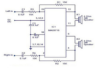
A 3-watt stereo amplifier circuit utilizing the MAX9710 integrated circuit (IC). The MAX9710 is a stereo audio power amplifier IC capable of delivering 3 watts of output to 4-ohm loads. It can operate from a single power supply ranging...
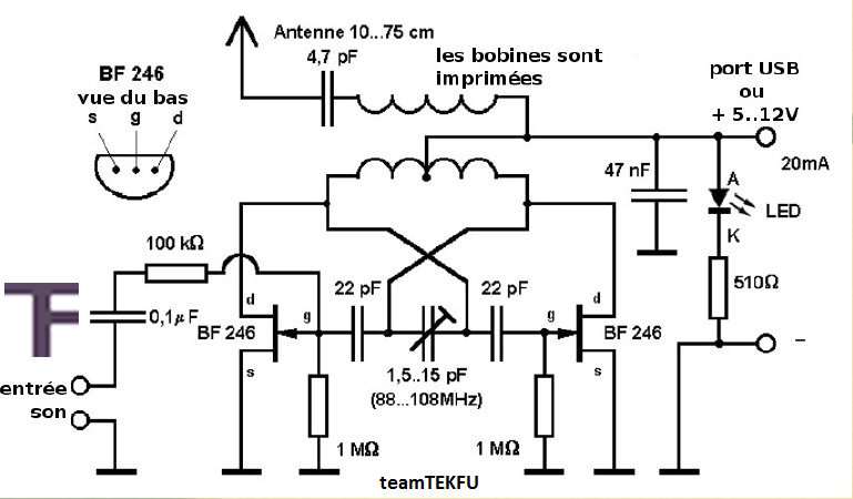
This compact FM transmitter has a range of approximately 50 meters and is designed for connection to a USB port. By utilizing multiple mini-transmitters, a comprehensive and engaging radio program can be created. The power supply through the USB...