
Current Loop Transmitter For Temperature Sensor
The current loop interface, commonly referred to as a 4-20 mA current loop, is a standard method for transmitting analog signals over long distances in industrial settings. This interface operates on the principle of current rather than voltage, which allows for better noise immunity. In environments with significant electromagnetic interference, such as factories or processing plants, the current loop can maintain signal integrity.
The typical configuration of a current loop involves a transmitter that generates a current proportional to the measured variable (e.g., temperature, pressure, or flow) and a receiver that interprets this current signal. The standard range for the current signal is between 4 mA and 20 mA, where 4 mA represents the lowest measurement (zero or minimum value) and 20 mA represents the highest measurement (full scale). This range provides a built-in fault detection mechanism; if the current falls below 4 mA, it indicates a problem, such as a broken wire or a malfunctioning transmitter.
To implement a current loop interface, components such as a power supply, a current transmitter, and a receiving device (such as a programmable logic controller or a data acquisition system) are necessary. The power supply typically provides the necessary voltage to drive the current through the loop. The transmitter can be a simple resistor or a more complex device that converts sensor readings into a proportional current output. The receiving device then converts the current signal back into a usable format for monitoring or control purposes.
The design of the current loop interface must consider factors such as loop resistance, voltage drop, and the power supply's specifications to ensure proper operation. Additionally, the use of twisted pair wiring can further enhance noise resistance, making the current loop a reliable choice for industrial applications. Overall, the robustness, noise immunity, and fault detection capabilities of the current loop interface make it a preferred choice in various industrial measurement and control systems.Current loop interface has been widely used in industrial environment because it`s robustness. Noise resistance and fail detection capability? made it suitable. 🔗 External reference
Related Circuits
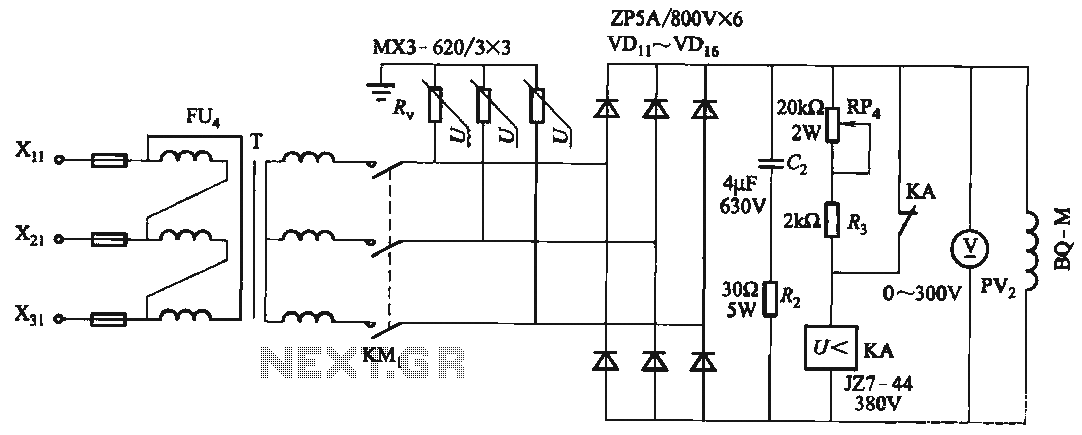
FIG T is the excitation transformer, R is a varistor, and there are rectifier diodes to protect against breakdowns from VDii to VD16; Rz and C2 provide resistive-capacitive protection. The circuit is designed to absorb voltage from the magnetic...
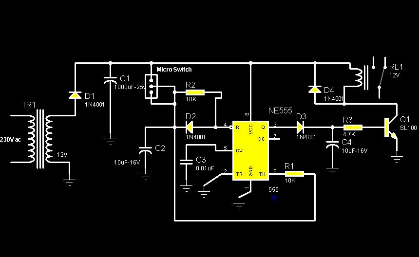
The circuit diagram illustrates a rotation sensor that activates a device, such as a motor or buzzer, when the circuit assembly is rotated. The design is based on the fundamental operation of a 555 timer. The rotation sensor circuit utilizes...
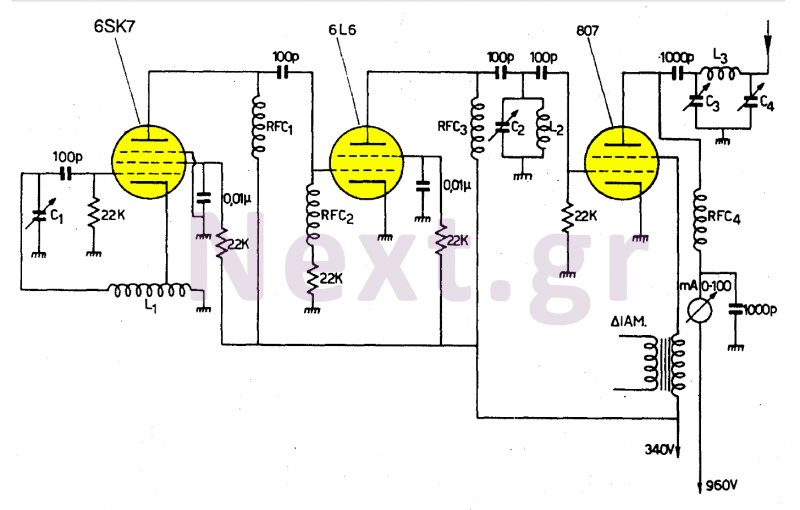
This transmitter operates in the shortwave range from 6 MHz to 22 MHz. Coil L1 serves as the shortwave oscillating coil for the 6SA7 vacuum tube and is commercially available. Capacitor C1 is a variable capacitor with a capacitance...
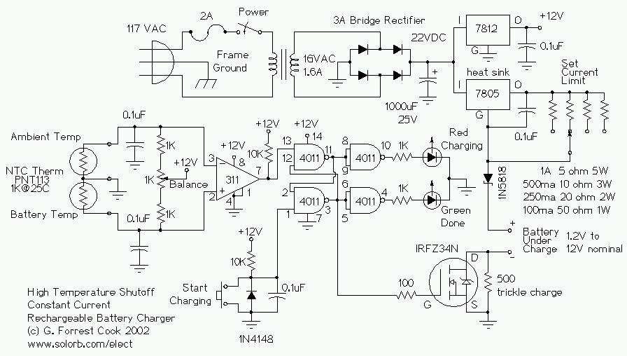
This circuit is designed for a temperature-controlled constant current battery charger, compatible with NiCd, NiMH, and other rechargeable cells. It operates on the principle that most rechargeable batteries exhibit an increase in temperature when they are fully charged. Overcharging...
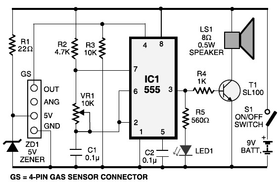
This schematic diagram represents an LPG gas leakage sensor alarm circuit powered by a 9V PP3 battery. A Zener diode (ZD1) is utilized to convert the 9V input into 5V DC, which is required to operate the gas sensor...
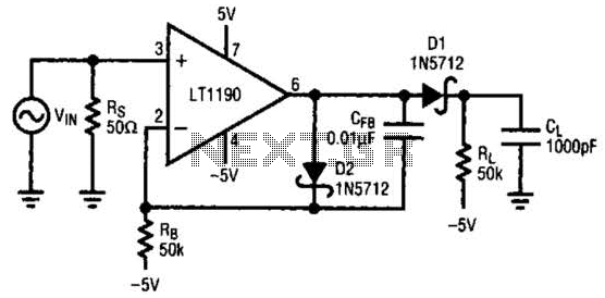
In this open-loop design, the detector diode is D1, and a level-shifting or compensating diode is D2. Load resistor RL is connected to -5 V, and an identical bias resistor RB is used to bias the compensating diode, also...