
Bi-Level Squelch
The proper operation of the squelch circuit in any FM radio is essential to avoid listening to discriminator noise. This is particularly critical in a repeater system. The primary function of a squelch circuit is to detect the presence of a radio signal and activate the speaker audio. The initial FM squelch circuit operated by detecting the presence of a signal through changes in the radio's Automatic Gain Control (AGC) voltage. However, this method was ineffective for weak signals, leading to the development of the noise-operated squelch. This method measures the amplitude of the discriminator white noise above the speech band, which is crucial. The audio from the receiver is divided into two bands: one from 300 to 3,000 Hz containing speech, and everything above 5,000 Hz considered noise, carrying no intelligible information. When a signal is detected, the discriminator output quiets, resulting in a drop in the amplitude of the white noise above the speech band. By converting this AC high-frequency noise to a DC signal, it can be measured and compared to a known reference voltage. When the noise signal is weaker than the reference, the squelch circuit activates the speaker; when stronger, the speaker is deactivated.
To prevent the squelch from opening on brief noise bursts, a resistor-capacitor timing circuit can be incorporated, which also necessitates a time delay for audio release to avoid chopping from fluttering signals like mobiles. This time delay is referred to as the squelch tail, which leads to a loud burst of discriminator noise at the end of each transmission until the delay concludes. Motorola addressed this issue with two solutions, one of which is the Micor bi-level squelch IC. The Micor was Motorola's first all-solid-state trunk mount mobile radio and marked a significant advancement in squelch circuit technology. The heart of this squelch system is the M7716 integrated circuit (IC), which is designed specifically for bi-level squelch applications. The M7716 is a complete squelch circuit on a chip, primarily found in the Micor radio.
The schematic of the M7716 complete squelch circuit indicates that it can be integrated into any model radio. Its open collector output from the 2N2222 can be connected to any repeater controller. The IC features two amplifier band-pass filter sections that filter out speech audio, allowing only high-frequency discriminator noise to pass. This is followed by a rectifier and two amplitude detectors. When the signal exceeds 1 µV (indicating full quieting), the logic circuit of the IC produces no squelch tail. Conversely, if the signal is below 1 µV (indicating noise), a squelch tail is generated long enough to prevent audio chopping on fluttering signals. The Micor bi-level squelch outperforms other systems in the field, eliminating squelch tail noise on repeaters and providing a clear indication of signal strength. If there is no squelch tail, full quieting is achieved; if a tail is present, the signal is noisy, offering a valuable diagnostic feature.
When transitioning a repeater to PL operation using a Com-Spec TS-32P PL board, the advantageous squelch tailless operation was lost, as the Com-Spec introduced a lengthy squelch tail upon loss of the PL tone, which was undesirable.As no one wants to listen to discriminator noise, the proper operation of the squelch circuit in any FM radio is vital. In a repeater, the squelch / COR is even more critical. The basic function of a squelch circuit is simple: detect the presence of a radio signal and turn the speaker audio on.
That`s really all they do. The first FM squelch circu its worked by detecting the presence of a signal by measuring changes in the radios AGC (Automatic Gain Control) voltage. This method worked poorly on weak signals so a better method was developed, the noise operated squelch.
The noise operated squelch works by measuring the amplitude of the discriminator white noise above the speech band. The phrase "above the speech band" is the critical part. Your receiver`s audio is split into two bands. One (from 300 to 3, 000 Hz) contains the speech. Everything above 5, 000 Hz is noise. No intelligence is carried there. When the radio hears a signal, the discriminator output begins to quiet. That is, the amplitude of the white noise above the speech band begins to drop. If we convert this AC high frequency noise to a DC signal, we can measure it. We can compare it to a known reference voltage as well. When the noise signal becomes weaker than the reference, the squelch circuit turns the speaker on. When the noise is stronger than the reference, the speaker is turned off. In practice we can add some timing as well. By adding a simple resistor / capacitor timing circuit to our squelch, we can keep it from opening on short bursts of noise that would be distracting.
This still leaves one problem. You can`t have the squelch circuit close the audio immediately either. If you do, the audio from fluttering signals like mobiles would be badly chopped. This requires the squelch to have a time delay on the release as well. This is called the squelch tail. The drawback to this is that at the end of every transmission, you hear a loud burst of discriminator noise until the time delay ends. Motorola developed two cures for this annoying problem. One I`ll discuss later. The other was the development of the famous Micor bi-level squelch IC. A little history here: The Micor was Motorola`s first true all solid state trunk mount mobile. It was also the high water mark for squelch circuit development. Since the use of PL and DPL (tone squelch) had not become universal yet, Motorola put a great deal of effort into the Micor`s noise squelch circuit.
The heart of the squelch is a special IC, the M7716 (also marked on early models as the SC6709 and M6709). The M7716 is a complete bi-level squelch circuit on a chip. As far as I know, it is found only in the Micor radio. The schematic shows the M7716 complete squelch circuit. Note that the circuit could be added to any model radio. Its open collector output from the 2N2222 can be interfaced to any repeater controller. The M7716 works like this. The IC contains two amplifier band pass filter sections. These reject the speech audio and pass only the high frequency discriminator noise. The amplifier filter is followed by a rectifier and two amplitude detectors. If the signal is above 1uV (that is full quieting) the IC`s logic circuit gives no squelch tail. If the signal is below 1uV (that is, there is some noise) there is a squelch tail. One long enough so there is no chopping on fluttering signals. Simply, the Micor bi-level squelch works better than anything else on the air. Not having a squelch tail on your repeater sounds great. Plus you can tell how strong your signal is into the repeater. If there is no squelch tail, you are full quieting; if there is a tail, you are noisy. A very handy feature! When I converted my repeater to PL operation (using a Com-Spec TS-32P PL board) I lost my wonderful squelch tailless operation.
The Com-Spec had a long squelch tail on loss of the PL tone that sounded awful. Taking a suggestion from Al Groff, K0VM, I came up with 🔗 External reference
Related Circuits
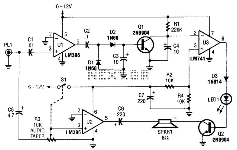
This circuit detects the presence of audio (voice) on the output of a scanner. If the scanner stops on a "dead carrier" or noise, the circuit mutes the speaker to avoid annoying noise. An operational amplifier amplifies speech and...
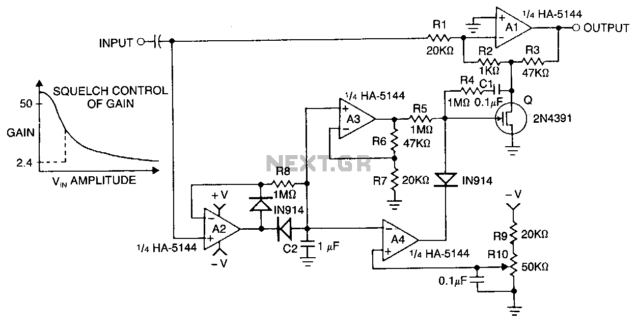
Automatic gain control (AGC) is a valuable feature found in various audio amplifier circuits, including tape recorders, telephone speakerphones, communication systems, and public address (PA) systems. This circuit utilizes a HA-5144 quad operational amplifier (op-amp) and a field-effect transistor...