
Scanner Voice Squelch
The circuit is designed to enhance the listening experience by automatically muting the output during periods of silence or noise, which is particularly useful in environments where a scanner is used for communication. The operational amplifier plays a crucial role in amplifying the audio signal, ensuring that even faint speech is detected and processed effectively.
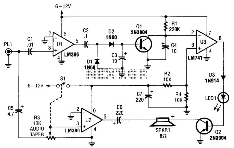
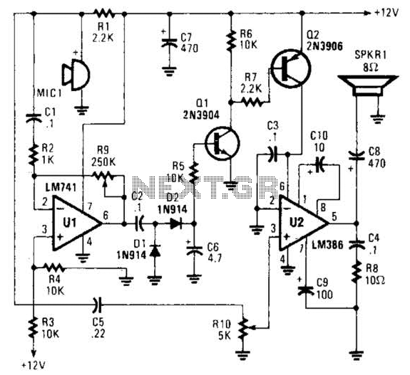
The rectifiers D1 and D2 are essential for converting the amplified audio signal into a suitable form for further processing. Switch Q1, controlled by the comparator U3, acts as a relay to mute the speaker when no valid audio signal is present. This function is vital to prevent listener fatigue caused by continuous noise or static.
The comparator U3 is configured to compare the amplified audio signal against a predefined threshold. When the audio signal exceeds this threshold, U3 activates switch Q1, allowing the audio to pass through to the speaker. Conversely, if the signal falls below the threshold, U3 will deactivate Q1, muting the speaker.
Transistor Q2 is used to complete the circuit path to ground, ensuring that the speaker is effectively muted when required. The audio amplifier U2 is responsible for driving the speaker with sufficient power, providing clear and audible sound output. The volume control resistor R3 allows for user adjustment of the audio level, enabling customization based on individual preferences or environmental conditions.
Finally, PL1 serves as a connection point for the scanner's speaker or headphone jack, allowing for versatile usage depending on the user's needs. Overall, this circuit effectively manages audio output from a scanner, enhancing the user experience by minimizing unwanted noise while ensuring clear communication when valid audio signals are present. This circuit detects the presence of audio (voice) on the output of a scanner. If the scanner stops on a "dead carrie r" or noise, the circuit mutes the speaker to avoid annoying noise. Ul amplifies speech and drives rectifier D1/D2 and switch Ql. Comparator U3 drives speaker switch Ql and indicator LED1. Q2 completes the speaker path to ground. U2 is an audio amplifier to drive the speaker. R3 is a volume control. PL1 connects to the scanner speaker or to the headphone jack. 🔗 External reference
Related Circuits
This project demonstrates the construction of a robot voice generator utilizing the HT8950 integrated circuit, which is a robust voice modulation IC. The circuit features a robot function, a vibrato function, and additional capabilities. The robot voice generator circuit employs...
This circuit is designed for low power operation and can be tuned to function within the frequency range of 87-108 MHz, achieving a transmission distance of 20 to 30 meters. The circuit utilizes a pair of BC548 transistors, which,...
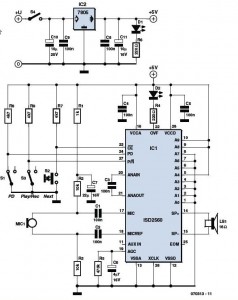
It is a common misconception that a robot voice generator box necessitates a large number of integrated circuits (ICs). In reality, the ISD2500 ChipCorder family of ICs from Winbond can effectively fulfill this requirement. The ISD2500 ChipCorder series represents a...

This circuit functions as a voice transmitter utilizing a pair of BC548 transistors. While these transistors are not specifically designed for RF applications, they still yield satisfactory performance. An ECM microphone insert from Maplin Electronics, order code FS43W, is...
An omnidirectional electret microphone is utilized to capture sound and convert it into an electrical signal. The output from the microphone is directed along two pathways. In the first pathway, the signal is routed to the inverting input at pin...
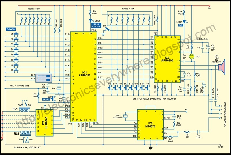
A circuit that allows for the operation of home appliances such as lights and water pumps from a remote location, such as an office. This system enables users to turn off appliances with their cellphones if they forget to...