
Bicycle speed circuit

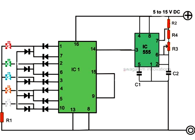
The bicycle speedometer circuit operates by converting mechanical movement into an electrical signal that reflects the speed of the bicycle. The core component of this circuit is the infrared light detector, which senses the passing of the wheel spokes as they rotate. Each time a spoke passes the detector, it interrupts the infrared light beam, generating a pulse. This pulse is critical for the timing mechanism of the circuit, as it is used to trigger the 555 timer IC configured in a monostable mode.
When the bicycle is in motion, the frequency of these pulses increases with speed. The 555 timer outputs a high signal for a duration determined by the resistor RP1 and the capacitor connected to it. This output is then converted into a DC voltage that is proportional to the speed of the bicycle. The voltage level is then displayed on a voltmeter calibrated to show speed in km/h. The calibration takes into account the circumference of the wheel, allowing for accurate speed readings based on the number of wheel rotations.
The components used in the circuit are selected for their reliability and performance. The NPN transistor (9014) serves to amplify the pulse signal from the infrared detector, ensuring that the 555 timer receives a strong enough signal to operate effectively. The trimmer potentiometers RP1 and RP2 provide adjustable resistance, allowing for fine-tuning of the timing characteristics of the circuit.
The physical layout of the circuit is also important. The infrared detector must be mounted securely to ensure consistent performance, and the bracket design is crucial for protecting the detector from ambient light while allowing it to function correctly. The use of carbon film resistors and metallized paper capacitors ensures that the circuit maintains stability and accuracy over time.
Overall, this bicycle speedometer circuit is an effective tool for cyclists, providing real-time feedback on speed and aiding in training and performance improvement. The design incorporates standard electronic components and principles, making it accessible for hobbyists and engineers alike.Cycling is our common means of transport, if accompanied by a bicycle speedometer, you will be able to master cycling speed, especially for cyclists , the usual training, a reasonable allocation of the way the speed, rhythm master speed, is a good method, bicycle speedometer circuit shown in Figure 5-33 below. The speedometer use bike ride line speed rotation of the wheel is proportional to the relationship between the frequency of rotation of the wheels is converted into a linear DC voltage ripple voltage and remove it from the electrical voltage meter displays the voltage value corresponding to the riding speed.
When riding infrared light detector per revolution of the wheel when moving hair a week, the next pulse, the crystal tube VT2 conduction generates a pulse to the next hop single trigger group consisting of an integrated circuit 555 -shot circuit. Riding faster time two pulses of infrared light emitted by the detector is shortened to increase the number of one-shot circuit outputs a high level, the average value of the DC voltage meter indication.
Meter scale in speed unit km / h, said the number of rotations of the bicycle wheel can be calculated based on the wheel circumference obtained, currently used bike 71cm (28in), 66cm (26in), 60cm (24in), 50cm (20in) 4 class , given the scale that is four available. 28in bike to calculate, such as when 40km / h speed line Chi, the wheels turning about 2.5 times / s.
Forgiving one-shot timing resistor RP1 and capacitance values can be used iookfl c2 and o. 47vF. Bicycle speedometer, the infrared light detector can be used for any infrared tube, LED and VT1 mounted on special brackets, the stent with a thin metal plate from a cross-sectional shape can refer lock structure and mount the front bicycle wheel spokes tops an obstruction, so that each revolution of the wheel, red light detector is shielded from the outside once. Transistor VT2 silicon NPN transistor 9014, selected about 120 betas. When the base integrated circuit NE555. Potentiometer RP1, RP2. They are made WH7 type trimmer potentiometers, remaining resistors are used RTX type 1 / 8W carbon film resistors.
Header with 91C2 type. Remaining capacitors are used CJ11 metallized paper dielectric capacitor.
Related Circuits
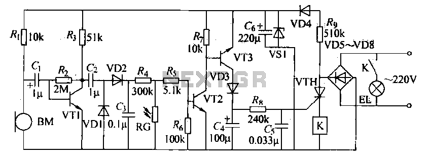
The voice circuits discussed in this section operate such that during daylight or in bright conditions, the voice-activated switch remains off, preventing the lamp from lighting. Conversely, in low-light conditions or at night, the sound control switch is activated....
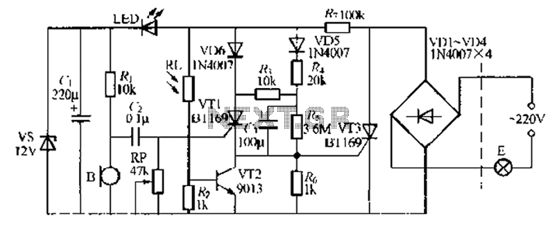
A relatively simple circuit for controlling a stair walkway light with a delay feature. The circuit has a drawback in that the voice activation is somewhat less sensitive, making it sometimes difficult to trigger with general conversation. However, it...
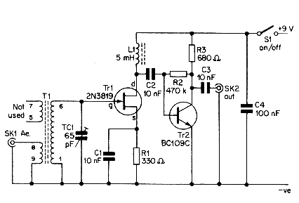
This simple aerial booster circuit design could serve as an alternative or a hobby project for creating an aerial booster device for Citizen Band (CB) radio. The aerial booster circuit is designed to enhance the performance of Citizen Band (CB)...
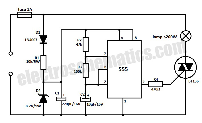
This 220V mains operated solid-state flashing lamp circuit utilizes a 555 timer integrated circuit (IC) to manage the ON and OFF durations of a triac that regulates power to the load. The circuit operates at a mains voltage of 220V,...
An LED light chaser circuit is an electronic configuration designed to illuminate a group of LEDs in a predetermined sequence. A commonly used integrated circuit (IC) for creating this type of LED sequencer circuit is the 4017. This IC...
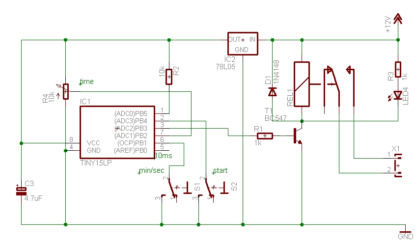
The time can be set using a potentiometer ranging from 1 minute to 1023 minutes, approximately 17 hours. A pushbutton initiates the timing process, activates a relay, and the timer will deactivate the relay once the set time has...