
How to Make a Simple Reverse Forward LED Light Chaser Circuit Using IC 4017

The LED light chaser circuit utilizing the 4017 IC is a versatile and engaging project suitable for various applications, including decorative lighting and visual displays. The circuit design begins with the 4017 IC, which is powered by a suitable voltage supply, typically between 5V and 15V, depending on the specific requirements of the LEDs used. The clock input at pin 14 can be driven by a square wave generator, such as a 555 timer configured in astable mode, which produces a continuous square wave signal at a desired frequency.
To achieve the desired LED chasing effect, the outputs of the 4017 are connected to a series of LEDs, with current-limiting resistors placed in series to prevent excessive current flow through the LEDs. The diodes connected to the outputs play a crucial role in modifying the output signals. By arranging the diodes strategically, the circuit can create a visual effect where the LEDs appear to chase in one direction and then reverse, producing a dynamic lighting pattern. The selection of diodes should consider their forward voltage drop and current rating to ensure compatibility with the overall circuit design.
The reset functionality, enabled by connecting pin 15 to pin 9, ensures that the sequence repeats seamlessly, allowing for a continuous display of the chasing pattern. The sequencing speed can be adjusted by varying the frequency of the square wave input, which changes the rate at which the LEDs illuminate. This flexibility allows for customization of the visual effects, making the circuit suitable for various decorative setups.
In summary, the LED light chaser circuit based on the 4017 IC is an excellent example of how basic electronic components can be combined to create visually appealing effects. The use of diodes to manipulate the output signals enhances the circuit's capabilities, allowing for both forward and reverse LED chasing patterns. This project serves as an educational platform for understanding digital counters, sequencing, and the application of basic electronic components in creating dynamic visual displays.LED light chaser circuit typically refers to an electronic configuration able to generate or illuminate a group of LEDs in somepredeterminedsequence. One popular IC 4017 is very commonly employed for making this type LED sequencer circuit. The IC basically is a Johnsons 10 stage decade counter/divider and can be used for many interesting light pat
tern generations, and may be used for variousdecorativepurposes. We all have probably learned a lot regarding circuits using the above IC for producing chasing light effects, however making the IC create "reverse" "forward" "chasing" pattern with LEDs is something many of us might not be acquainted with. The IC has 10 outputs which generate the sequencing high outputs in the order of the pin outs - 3, 2, 4, 7, 10, 1, 5, 6, 9, 11.
The sequencing takes place in response to a frequency applied at pin 14 of the iC Pin 13 is used clock inhibit inhibit and will stall the circuit if connected topositivesupplyterminal, however connecting it to ground makes everything normal, so we connect it to ground. The pin 15 of the IC is connected to the second last pin 9 of the IC, whichmeansthe output resetsevery-timethe sequencing reaches pin 9m, and the moment this pin goes high, the IC repeats the action byresettingthe system.
Pin 14 is the clock input and requires to be fed with asquarewave frequency, easy obtainable through any astable oscillator made from ICs like IC 555, IC 4049, transistors etc. Looking at the figure, we see that basically the IC is arranged in its normal sequencing or chasing mode, however the clever introduction of the diodes at the outputs of the IC make thesequencingappear to be reversing and forwarding from start tofinishand vice versa.
The diodes just make the outputs of the ICalignin a to and fro manner by forcing 5 outputs to move in a forward chasingpattern, while the following 5 outputs are redirectedtowardthe same LEDs but in theoppositedirection, making the pattern look like a to and fro chasing motion. 🔗 External reference
Related Circuits
The oscillator that consists of a quartz crystal can be classified into two types: the parallel resonant type crystal oscillator and the series resonant type crystal oscillator. The parallel resonant type crystal oscillator and its AC equivalent circuit are...
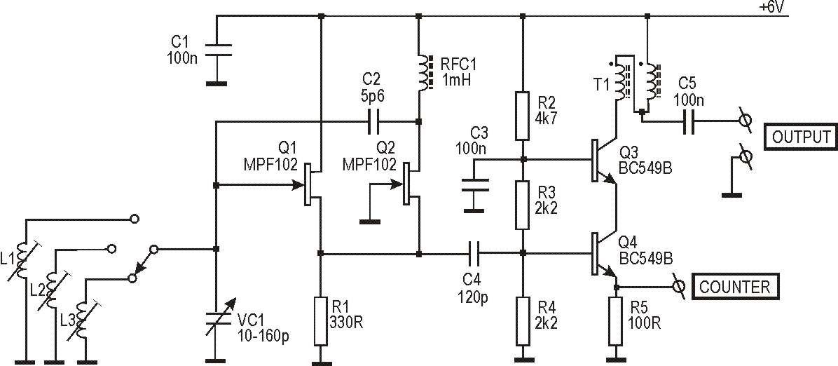
This circuit originated from work on two antenna analyzers, which are detailed elsewhere on this site. Both instruments incorporate an RF signal generator that serves as the signal source for driving the impedance bridge and detectors used to measure...
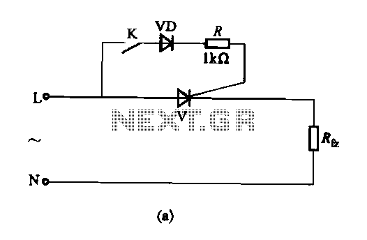
The thyristor AC switch circuit is not triggered, due to its simplicity, cost-effectiveness, and non-contact operation, making it widely utilized. The circuit is illustrated in Figure 16-43. It consists of single-phase thyristor switching circuits. Figure 16-43 (a) depicts a...
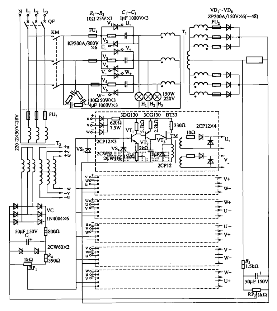
A three-phase thyristor power regulator circuit designed for plating applications, capable of handling currents from 1200A to 6000A at a voltage of 10V. The circuit comprises a main circuit, a trigger circuit, synchronous power components, and a voltage negative...
An adaptable siren generator circuit with multiple applications is presented. It is based on a 556 twin-timer chip, IC1. One timer section generates an audio tone that is directly coupled to the driver transistor, TR1. The other half of...
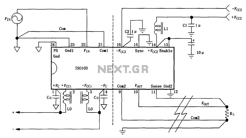
The basic connection circuit for the ISO103 signal and power supply is illustrated. Each power supply terminal must include a bypass filter. If the isolated power supply output current exceeds 15mA, it is advisable to utilize an external filter...