
Bidirectional motor control (driver) circuit for Robotics beginners
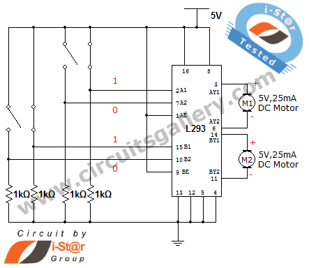
The L293D IC serves as a pivotal component in the control of DC motors, facilitating both forward and reverse motion through its H-bridge configuration. This configuration allows for the direction of current flow to be reversed, enabling the motor to rotate in either direction based on the input signals provided to the IC.
The dual H-bridge design of the L293D allows for the control of two motors independently, making it suitable for applications requiring synchronized or independent motor operation. Each channel is capable of handling a continuous current of 600 mA, which is sufficient for small to medium-sized DC motors commonly used in robotic applications.
The operational voltage range of 4.5 to 36 V DC provides flexibility in selecting power sources, accommodating a variety of motor specifications. The internal high-speed clamp diodes are critical for protecting the circuit from voltage spikes generated when the motor is turned off, which can otherwise damage the driver IC.
In addition to these features, the L293D IC incorporates high noise immunity, which is essential in noisy environments often encountered in robotic systems. The internal ESD protection safeguards the circuit from electrostatic discharges that could compromise performance. The thermal shutdown feature prevents overheating by disabling the driver when the temperature exceeds safe operating limits, thereby enhancing the longevity and reliability of the circuit.
Overall, the L293D motor driver IC is a robust solution for controlling DC motors in various robotic applications, providing essential features that ensure safe and efficient operation. Proper integration of this IC into a circuit design allows for precise control of motor direction and speed, making it an invaluable tool for robotics enthusiasts and professionals alike.How can we rotate a DC motor in clockwise and anti clockwise directions Or how can we rotate a motor in forward and reverse direction These are the popular question asked by many of the robotic beginners. DC Motor (control) driver circuits are the essential circuit of robotics workshop. L293D IC is widely used for implementing DC motor control c ircuits. It is a dual H bridge motor driver IC, that is it can drive two DC motor simultaneously and is available in 16 pin DIP package. We have already posted H Bridge motor driver circuit with transistors. L293 driver IC has a current capacity of 600mA per channel and a wide supply voltage range (4. 5 to 36V DC). They are integrated with internal high speed clamp diodes for inductive spike protection. Other superior features of L293 are high noise immunity, internal ESD protection, thermal shutdown and separate input supply for each channel.
🔗 External reference
Related Circuits
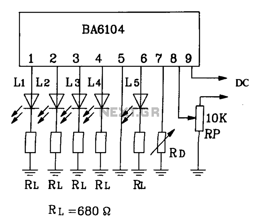
BA6104 is a five-digit LED level meter driver integrated circuit (IC) that features a basic application circuit. The input stage employs a PNP transistor with a composite base input, resulting in high input impedance. The output stage is configured...
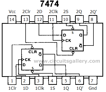
Digital counters have various applications in electronic circuits. In digital electronics, counters are utilized in different situations. This article presents the concept of a ring counter circuit, which functions as a register counter. An animation and simulation video of...
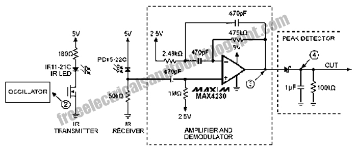
The following circuit illustrates an Infrared Proximity Sensor Circuit Diagram. This circuit is based on the MAX4230 integrated circuit. Features include a 10 kHz oscillator. The Infrared Proximity Sensor Circuit utilizing the MAX4230 integrated circuit is designed to detect the...
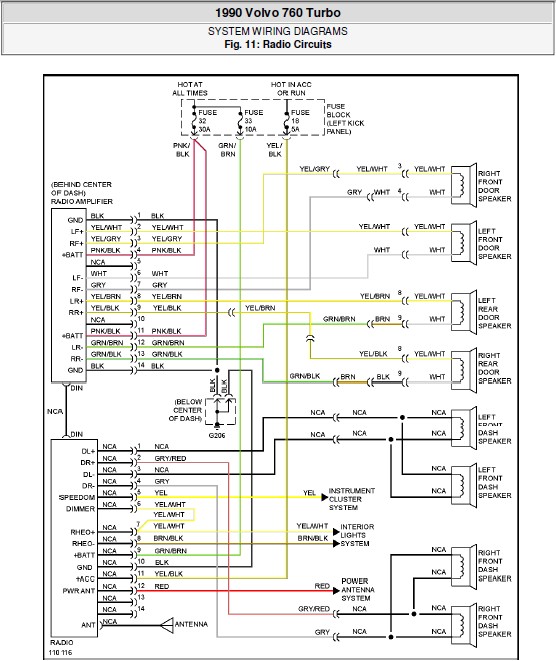
The following document contains the system wiring diagram of the radio circuit for the Volvo 760 Turbo 1990. Please note that this is a system wiring diagram, not a schematic diagram. Download the radio circuit system wiring for the...
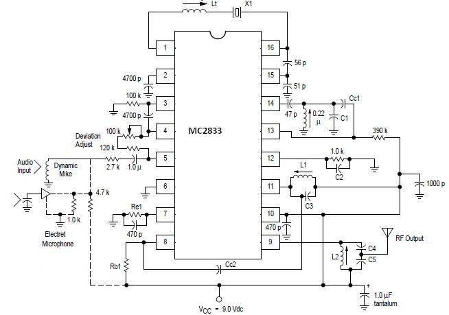
A simple FM transmitter circuit can be designed using the MC2833 integrated circuit, which is intended for cordless telephone and FM communication applications. This circuit includes a microphone amplifier, a voltage-controlled oscillator, and two auxiliary transistors. The final output...
Today, nearly all computers are equipped with logic blocks designed to implement a USB port. In practice, a USB port can deliver over 100 mA of continuous current at 5V to the peripherals connected to the bus. This capability...