
Ring Counter Circuit Working Principle with Animation and Video
A ring counter is a specific type of counter that operates on the principles of shift registers and is characterized by its ability to circulate a single high signal (logic 1) among multiple flip-flops. The number of states in a ring counter is determined by the number of flip-flops utilized in the circuit. In a 4-bit ring counter, for instance, the counter will have four unique states, each represented by a different arrangement of the high signal among the flip-flops.
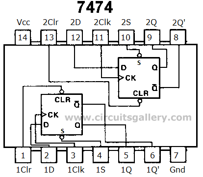
The circuit design typically involves using D-type flip-flops (7474), which are triggered by a common clock signal. The clock pulse synchronizes the operation of all flip-flops, ensuring that data is shifted in unison. The first flip-flop receives a preset input that initializes its output to high. As the clock pulses are applied, the high signal shifts through the flip-flops in a sequential manner. After the last flip-flop, the low output is fed back to the input of the first flip-flop, completing the cycle.
In practical applications, the ring counter can be used in various digital systems, such as frequency dividers, sequence generators, and timing applications. The simplicity of the design allows for easy implementation, while its ability to maintain a defined sequence of states makes it suitable for applications requiring a predictable output. The use of a push-to-off switch for the preset function provides a user-friendly method to reset the counter, enhancing the versatility of the circuit. Proper attention must be given to the connections of the preset pins to ensure reliable operation in real-world applications.Digital counters have several applications in electronics circuits. Counters in digital electronics are used at different situations. Here we are going to deliver the idea of aRing counter circuit, which is a register counter. Working animation and circuit simulation video of ring counter are also given along with this article. A ring counter is f ormed by feeding the output of a shift register to its own input. The data pattern enclosed within the shift register will re-circulate as with respect to the clock pulse. Ring counter is one of the shift register applications. We have already posted Johnson counter circuit with animation. With little modification on ring counter we can obtain Johnson counter circuit. A ring counter has N states where N` is the number of flip-flops. So let`s discus about digital counter circuit design (Ring counter) in detail with animation/ simulation.
This counter is a circulated shift register. Here a 4 bit shift register is implemented with 7474 flip flops. This is a synchronous counter because clock signal is common for all flip flops. Preset` pin of 1st unit is connected to Vcc via a switch (Push to OFF switch). Preset pin is used to set the output of a flip flop to logical high (1)forcefully. The Presets` of other flip flops are directly coupled to Vcc in order to work properly because these pins are active low logic pins (This connection is not shown in above circuit. For simplicity it is removed). But don`t forget to connect it while you are implementing practically. This output will be shifted to the next flip flop during the next clock pulse and so on. At the same time the low output from last flip flop is shifted to the input of 1st flip flop. 🔗 External reference
Related Circuits
This webpage outlines the radio transmitter unit that was part of the Cirrus One rocket mission in April 2001. The transmitter was included as a payload due to concerns about recovery challenges if the rocket drifted far downrange after...
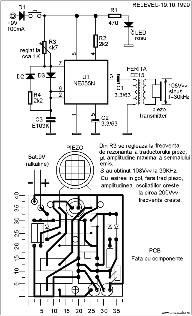
This ultrasonic dog repeller circuit is designed to deter aggressive dogs. It is constructed using the well-known 555 timer circuit, a buzzer, and a small ferrite transformer. The ultrasonic dog repeller circuit operates by emitting high-frequency sound waves that are...
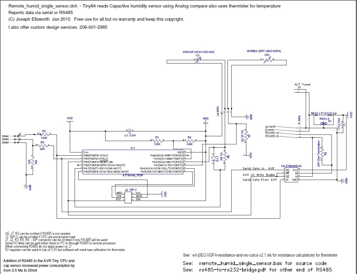
This document explains how to read a capacitive humidity sensor directly from a microcontroller using one resistor, one diode, the sensor, and two I/O lines. This method does not use an ADC but measures the time required to charge...

This is a circuit for an accelerometer amplifier. It is a straightforward circuit. A precision accelerometer requires an inverting mode amplifier since these devices typically output charge. This amplifier converts charges into a voltage output. The circuit presented below...

This is a design circuit for a low-cost FM antenna booster that can be used to listen to programs from distant FM stations clearly. The antenna FM booster circuit comprises a common-emitter tuned RF preamplifier wired around the VHF/UHF...
A school operates with a total of eight periods, each lasting 45 minutes, and includes a 30-minute lunch break following the fourth period. A bell is used to signal the start of each class, the end of each period,...
Warning: include(partials/cookie-banner.php): Failed to open stream: Permission denied in /var/www/html/nextgr/view-circuit.php on line 713
Warning: include(): Failed opening 'partials/cookie-banner.php' for inclusion (include_path='.:/usr/share/php') in /var/www/html/nextgr/view-circuit.php on line 713