
BINARY DECIMAL LED DISPLAY VERSIONS OF THE SIMPLE FREQUENCY COUNTER
This frequency counter circuit is designed to provide a clear and accurate frequency readout for amateur radio applications, particularly in QRP setups. The use of 74HCT390 chips enables more precise counting, and the dual /10 divider configuration allows for a more efficient LED display. The RF preamplifier, implemented with a 74HC00, enhances sensitivity while eliminating the settling time issues associated with traditional transistor amplifiers. This design focuses on achieving optimal performance and accuracy, ensuring reliable frequency measurements across various operating conditions. The careful calibration process, reliant on adjusting the reset pulse length, further enhances the counter's accuracy, making it a valuable tool for frequency monitoring in QRP equipment. Overall, this circuit represents a significant advancement in frequency counter technology, providing users with a high level of functionality and precision.There are other display methods than the original 8 led frequency counter has. They are perhaps easier to read and may have a format that fits better to the front of your QRP equipment. Here some examples of binary decimal displays are given. Mostly the the counter is made without the MHz position, only the kHz position is used to read the VFO fre
quency within a 100 kHz segment. This counter uses only 7 leds for reading the frequency in a 100 or 50 kHz segment. The counter starts counting at zero at each multiple of 100 or 50 kHz. Gating is done after the first /2 divider. In this version, also the preamplifier is deleted and 74HCT390 chips are used instead of a 74HC390 for maximum sensitivity. The first /2 divider is adjusted for maximum sensitivity with a DC bias voltage. Gating is done after this first /2 divider. Of course it is also possible to use 74HC chips plus the RF preamplifier. In this case, the RF preamplifier is supplied by the 5V supply and not by the gating pulse. The advantage is that the RF amplifier is not switched on/off by the gating signal which might influence your VFO frequency due to the varying load.
The least significant led (2 or 1 kHz) works like an analog scale. It slowly varies in brightness when the frequency is changed. Therefore, the frequency reading is much better than the value of that led. The 74HC4040 in the original 8 led counter is replaced by a 74HC390. This chip has two /10 dividers so that we will have that new display with 2x4 leds instead of the 1x8 led display. A 74HC00 (do not use a HCT) is added, one NAND is used as RF preamplifier to increase the sensitivity and as buffer between the VFO and counter, another as an RF gate switch to start and stop the counter.
The unused inputs of the two remaining NAND`s are grounded. Using a 74HC00 instead of the transistor amplifier eliminates the problems with the settling time of the RF transistor amplifier of the original two chip frequency counter. The chip is even cheaper than the transistor but needs more supply current! The 74HC4060 oscillator with the 4096 kHz X-tal generates a frequency of 500Hz. Only the +5V half period is used for counting. During the +0V half period, the leds are displaying the frequency, during the +5V half period, they are off and the 74HC390 is counting the frequency.
At the beginning of the counting period, the 74HC390 is reset by the short reset pulse from the 100 pF/Rcal differential network. The gating is very critical as a 1 to 0 transition from the 74HC00 gate will cause an extra count. This does not occur when the gate switches off, then the output goes from 0 to 1 (or 1 to 1). But when the gate switches on while the input is 1, the output of the gate is changes from 1 to 0. However, during this moment the reset pulse is active, preventing that extra count. Normally, the calibration is done by adjusting the crystal frequency with a trimmer. But not here! Due to the 100pF capacitors, the oscillator frequency is lower than the crystal frequency. The resulting gating pulse is a little too long. But the frequency measurement time is the length of the gating pulse minus the reset pulse. Calibration of the frequency counter is done by changing the length of the reset pulse (depending on Rcal value).
Select the Rcal value for a correct display of a reference frequency. At 30 MHz, the frequency error was +300 Hz. At 10 MHz, the error was 100 Hz. In the MHz position, the accuracy is the same as in the kHz position because the same gate pulse and reset pulse are used. Supply current including a 78L05 stabilizer is 10 mA with an input signal and 50 percent of the leds on, 25 mA without input signal as the supply current of the 74HC00 is much higher without an input signal.
🔗 External reference
Related Circuits
This is the construction guide for the 5301 wideband fuel mixture display kit. The 5301 is the Tech Edge version (rather than the Jaycar version) of the modified Silicon Chip FMD design, and it features, compared to the original...
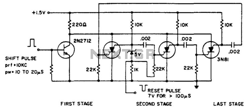
The ring counter operates from 1.0 to 6.0 V and requires only 6 mW at 1.5 V. The reset pulse activates the first stage with its trailing edge. The maximum shift pulse width increases with voltage and approaches 70...
Yesterday, a decision was made to abandon watching a movie in favor of building a binary clock. After some contemplation on the programming aspect, the project was successfully completed. The clock operates effectively, and a detailed explanation of the...

A10-V zener diode is utilized to extend the measurement range of a voltmeter from 0-5 V to a range of 10-15 V. An LED bar graph illuminates one segment for every 0.5 V increase above 10 V. Additionally, the...
This frequency doubler uses one CMOS quad, two input NAND gate package type 4011. The frequency doubler proper consists of an inverter IC1B, two differentiating networks R1/C1, R2/C2 and NAND gate IC1A, IC1C and IC1D function as input and...
The bi-directional sequencer utilizes a 4-bit binary up/down counter (CD4516) and two "1 of 8 line decoders" (74HC138 or 74HCT138) to create the well-known "Night Rider" display. A Schmitt Trigger oscillator generates the clock signal for the counter, with...