
Night Rider 16 Stage Bi-Directional LED Sequencer circuit
The bi-directional sequencer circuit is designed to produce a visually engaging "Night Rider" effect through the use of a 4-bit binary up/down counter (CD4516) that counts in both directions based on the input from an external control mechanism. The CD4516 counter is a versatile device that allows for both counting up and down, making it suitable for applications requiring reversible counting sequences.
The circuit employs two 1 of 8 line decoders (74HC138 or 74HCT138) to decode the binary output from the counter into a specific output line, illuminating LEDs in a sequential manner that mimics the original "Knight Rider" light pattern. The choice between the 74HC138 and 74HCT138 is critical; the 74HC14 Schmitt Trigger inverter is preferred for its higher input threshold levels, ensuring reliable operation in TTL logic environments.
A Schmitt Trigger oscillator is integrated to provide a stable clock signal for the counter, with its frequency adjustable via a 500K potentiometer. This adjustability allows for customization of the speed at which the display animates, providing flexibility for different applications.
The circuit also includes a Set/Reset latch implemented with two Schmitt Trigger inverters. This latch controls the direction of counting by determining whether the counter should increment or decrement. When the counter reaches its maximum count of 1111, the output at pin 7 goes low, setting the latch and switching the counting direction to decrement. Conversely, when the counter reaches its minimum count of 0000, the latch resets, enabling the counter to increment on the next clock pulse.
The output from the counter is structured so that the three least significant bits (Q0, Q1, Q2) are connected to both decoders in parallel, facilitating simultaneous decoding. The most significant bit (Q3) serves as a selector, determining which decoder is active based on the current count. This configuration ensures that the LEDs light up in a sequential pattern, enhancing the visual effect of the display. Overall, this circuit design offers a robust solution for creating dynamic lighting effects in various electronic projects.The bi-directional sequencer uses a 4 bit binary up/down counter (CD4516) and two "1 of 8 line decoders" (74HC138 or 74HCT138) to generate the popular "Night Rider" display. A Schmitt Trigger oscillator provides the clock signal for the counter and the rate can be adjusted with the 500K pot.
Two additional Schmitt Trigger inverters are used as a S ET/RESET latch to control the counting direction (up or down). Be sure to use the 74HC14 and not the 74HCT14, the 74HCT14 may not work due to the low TTL input trigger level. When the highest count is reached (1111) the low output at pin 7 sets the latch so that the UP/DOWN input to the counter goes low and causes the counter to begin decrementing.
When the lowest count is reached (0000) the latch is reset (high) so that the counter will begin incrementing on the next rising clock edge. The three lowest counter bits (Q0, Q1, Q2) are connected to both decoders in parallel and the highest bit Q3 is used to select the appropriate decoder.
🔗 External reference
Related Circuits

This is a versatile Low-Frequency Oscillator (LFO) designed for various modulation applications. The frequency of the LFO can be controlled by voltage, enhancing the range of sound possibilities. The pulse width of the rectangular wave can be adjusted between...
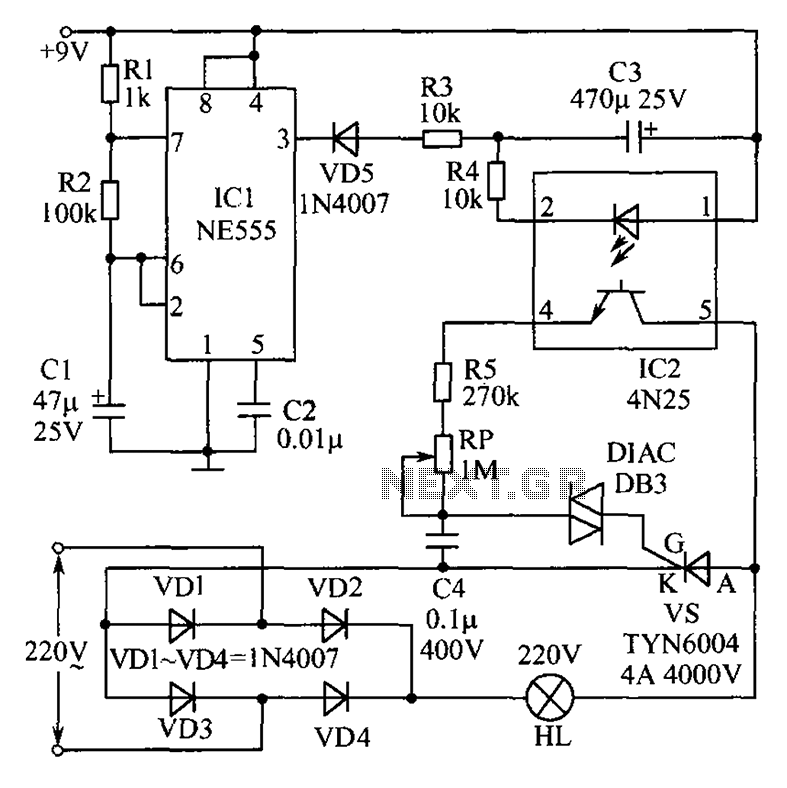
This circuit features an appealing Christmas lights setup. Upon activation, the lights (HL) gradually increase in brightness. Once they reach maximum brightness, they automatically dim, and upon reaching the lowest brightness, they gradually brighten again, creating a smooth transition...
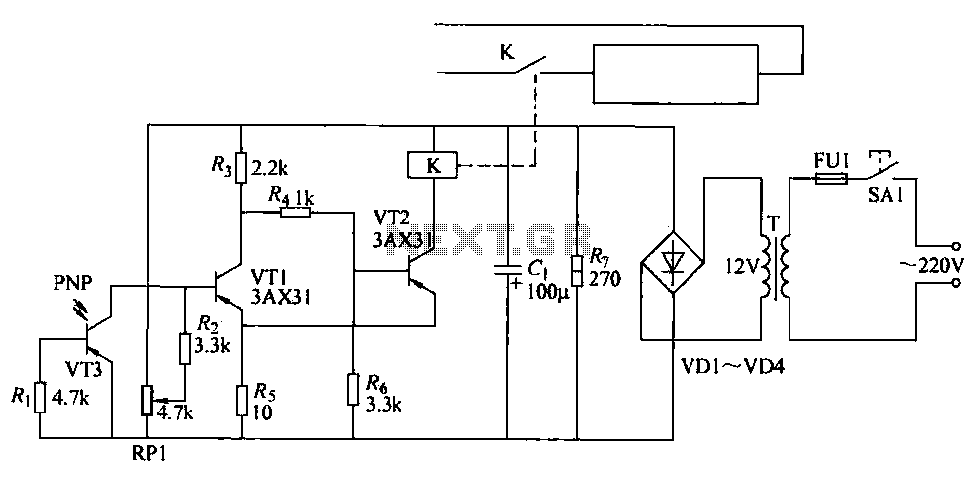
The cutter is safeguarded by a printed circuit phototransistor designed to prevent accidental activation of the cutter switch during manual feeding. In the event of manual feeding, the automatic paper cutter can be controlled to shut down. A relay...
This was designed to flash a pair of LEDs to be mounted on the wing tips of a Parkzone Citabria R/C (remote control) airplane. The unmodified Parkzone Citabria only weighs 20 grams (about 0.7 oz), so weight, and therefore...
A passive light-emitting diode output level indication circuit. This circuit utilizes a light-emitting diode (LED) to provide a visual indication of the output level from a given source. The design is characterized by its passive nature, meaning it does not...
I needed a pulsating light for a certain signaling. Voltage was 230V. So I decided to make a simple circuit, consisted of a LED diode, two capacitors, two resistors, a diac and a diode. Activity of the circuit is...