
BiQuad Filter Circuit Diagram using LM3403 Quad Op Amp
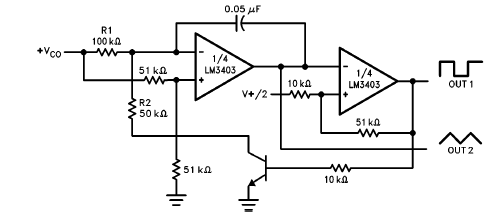
The LM3403 op-amp family, particularly the LM3303 model, is designed for applications requiring high precision and stability. The monolithic structure contributes to reduced noise and improved performance in signal processing tasks. The biquad filter circuit depicted in the schematic utilizes the quad op-amp's capabilities to achieve a specific frequency response characterized by a center frequency of 1000 Hz.
In this configuration, the bandwidth of 100 W indicates the range of frequencies that the filter will allow to pass through, while the center frequency gain (TBP) and bandpass notch gain (TN) being set to 1 imply that the filter will neither amplify nor attenuate the signal at the center frequency and notch frequencies, respectively.
The resistors and capacitors in the circuit are critical in defining the filter's characteristics. The resistor R, valued at 160 kOhm, works in conjunction with R1, R2, and R3 (each 1.6 MOhm) to set the gain and frequency response. The capacitor C, valued at 0.001 µF, plays a vital role in determining the cutoff frequencies and the overall behavior of the filter. The calculations for Q and fo are essential for ensuring that the filter meets the desired specifications.
The reference voltage VREF, set to half of the supply voltage (0.5 * Vcc), provides a stable operating point for the op-amps, ensuring linear operation within the specified range. The relationships between the resistors, as defined by Q, TBP, and TN, allow for flexible tuning of the filter characteristics, making this configuration suitable for various signal processing applications in audio, communications, and control systems.This LM3403 op amp family including LM3303 known to be a monolithic quad op amp which have high gain, a compensated internal frequency that will assure a wide range of voltages can be operated from both single and/or dual power supply. The circuit diagram shown Bi Quad Filter using LM3403 Quad Op Amp. As you can see, it uses example that fo=1000Hz , BW=100W, TBP (center frequency gain)=1, TN (bandpass notch gain)=1, R=160 kOhm, R1/2/3=1. 6 MOhm, and C=0. 001uF; where Q= BW/fo, fo= 1/(2*phi*R*C) VREF=0. 5*Vcc, R1=Q*R, R2= R1/TBP, R3= TN*R2, and C1= 10*C. 🔗 External reference
Related Circuits
The preamp featured is very straightforward to make on the PCB, and has an innovative tone defeat function. Rather than completely disable the tone controls, they are massively de-sensitised, and when "defeated" have a maximum range as shown in...
This circuit enables audio monitoring of a remote location, functioning as both a room monitor and a baby alarm. It can be powered by a 12-volt battery or a mains power supply. The interconnection utilizes three wires, allowing for...
How many speakers can be attached to this amplifier, and what are the impedance and wattage values of these speakers? Please respond to my email. Sir, you made this amplifier, and it works properly for a lifetime. Which transformer...
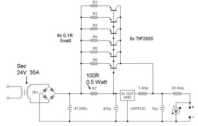
A 12 Volt 35 Amp power supply can be constructed using the LM7812 voltage regulator to provide a stable 12 Volt DC output. The power supply employs TIP2955 transistors as the main power regulators, with a configuration that utilizes...

It is embarrassing to acknowledge that the blog post from April 29 contained several schematic errors of my own making, particularly in the variation of Morgan Jones's circuit. One of the resistor values was incorrect by a factor of...
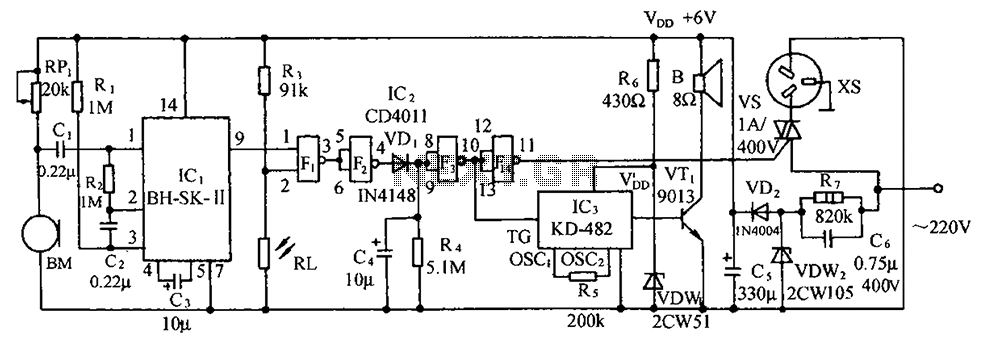
The circuit illustrated includes a sound transducer sensing switch, an electrical light control switch, an SCR control circuit, a vocal music circuit, and an AC step-down rectifier circuit. The circuit comprises several interconnected components that serve distinct functions, allowing for...