
Broskie auto-bias circuit

The schematic includes the following key components:
1. **OpAmp**: This operational amplifier is central to the feedback mechanism, comparing the cathode voltage to the reference voltage and adjusting the grid-bias voltage accordingly.
2. **Resistors (R1, R2)**: These resistors are equal in value and help set the reference voltage for the DC servo circuit.
3. **Capacitors (C1, C2)**: These capacitors are also equal in value and play crucial roles in charging and discharging to maintain the bias voltage.
4. **Clipping Diode**: This diode is essential for preventing excessive error signals from affecting the operation of the circuit, ensuring that the bias voltage remains stable within the desired operational window.
The circuit's design allows for effective bias management, ensuring that the amplifier operates optimally across its intended range while minimizing distortion and maintaining fidelity. The careful selection of component values and the configuration of the feedback loop are critical for achieving the desired performance characteristics.Considering that I had complained of a schematic typo from Siliconix, it is doubly embarrassing that that April 29`s blog held a few schematic typos of my own creation: in the variation on Morgan Jones`s circuit one of the resistor`s values was off by a decade and, more damning, one of the OpAmp`s inputs was reversed. Below, the corrected schemati c is displayed. (The 4/29 blog has been updated to reflect these corrections. ) The generic DC servo circuit (shown below) works perfectly as long as the amplifier does not amplify asymmetrical signals and as long as the output stage`s current swings are within in the class-A window of operation. However, once the output stage jumps out of class-A into class-AB operation, the DC servo will see a net DC increase at its inverting input and it will strive to bring the amplifier back into line with its reference voltage, but at the same time the capacitor will begin to charge to higher voltage, which will throw the bias voltage off (negatively) until the input signal subsides enough to let it discharge back to its idle value, as shown in the graph below.
The graph above shows the tube`s current conduction in hot pink, the grid bias voltage in blue, and the capacitor`s voltage differential in green. The signal burst excessively charges the DC servo`s capacitor and its output voltage is thrown off the mark by over half a volt (602mV).
The principle behind the clipping-style auto-bias circuits is also simple: monitor the tube`s current conduction while it is operating in class-A; ignore its AC conduction beyond class-A, when the tube moves into class-B. The clipping diode shorts to ground error signals greater than its forward voltage. In other words, the clipping diode`s forwards voltage creates a window that extends from 0V to the cathode-to-anode voltage required to turn the diode on (silicon diodes also have cathodes).
By setting the DC servo`s reference voltage to half of the diode`s forwards voltage, we ensure that the window of current encompasses the extent of class-A operation that the tube(s) can undergo, without one tube cutting off, while the other conducts beyond the window`s top edge. This plan works perfectly with no input signal; well with large input signals that extend deep into class-B; not so well with input signal just beyond class-A operation of the output tubes.
What if we don`t clip the error signal What if, instead, we use it to prevent the DC servo`s capacitor`s excessive charging from throwing the bias voltage off Well, that`s the idea behind the Broskie auto-bias circuit. How does it work The triode`s idle current must be great enough to establish the same voltage across the cathode resistor as the diode`s forward voltage, as this voltage is used as the servo`s reference voltage.
(Imagine that the diode that attaches to the tube`s cathode has been removed from the circuit, which it effectively is at idle). The OpAmp compares the cathode voltage to its reference voltage and then establishes and maintains grid-bias voltage required to meet this compulsory idle current.
Now, as long as the tube runs within the boundary of twice the diode`s forward voltage (Vd) at its cathode, the triode will operate in pure class-A and the DC servo will handle setting the bias voltage quite nicely. Once the tube leaves the confines of class-A, however, its cathode voltage will exceed twice Vd and the diode attached to the cathode will begin to conduct, charging C2 as a result.
Since capacitors C1 and C2 are equal in value, as are resistors R1 and R2, the rate of charging will be the same between both capacitors. In other words, the DC servo`s reference voltage will be thrown off in a matching way as the servo`s own capacitor is thrown off.
It`s much like docking a boat to a floating dock: no matter how much the tide rises or falls, the boat will remain in the same relation to the dock. In the schematic above, we see all 🔗 External reference
Related Circuits
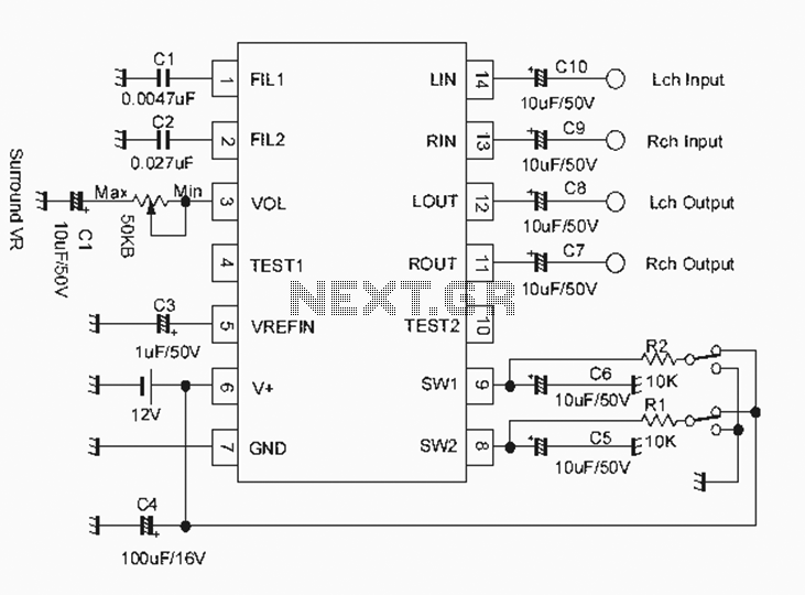
The NJM2701 3D surround sound audio processor integrated circuit can be designed into a very simple 3D surround sound system. The NJM2701 reproduces 3D surround sound using only two speakers and is suitable for various audio applications, including micro-components,...
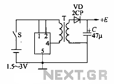
A DC booster circuit is illustrated in the figure, which represents a step-up transformer circuit diagram. The step-up transformer (T) can be utilized to power small transistor radios. The winding ratio can be adjusted to achieve the desired output...
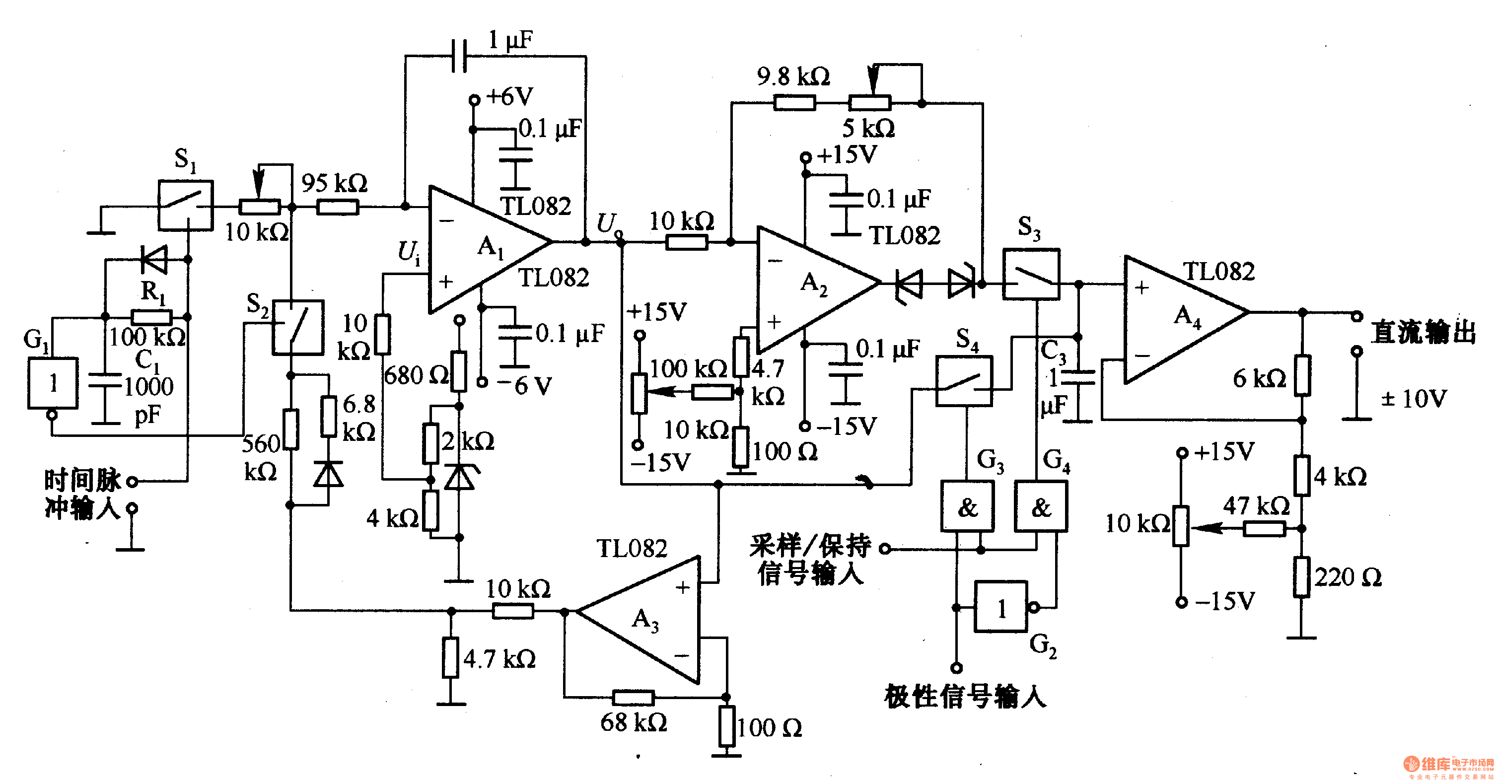
This circuit is designed for pulse width (time) to voltage conversion. According to the component parameters in the diagram, it can convert a pulse width of 0.1 seconds into an output voltage of 10V. When a conversion pulse is...
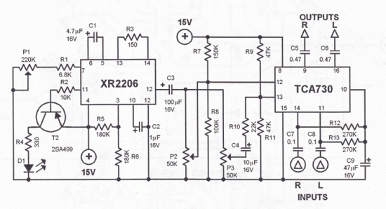
This tremolo effect circuit utilizes the XR2206 and TCA730 integrated circuits, designed for electronic balance and volume regulation with frequency correction. The circuit is beneficial for stereo channels and can simulate the Lesley effect, also known as the rotating...
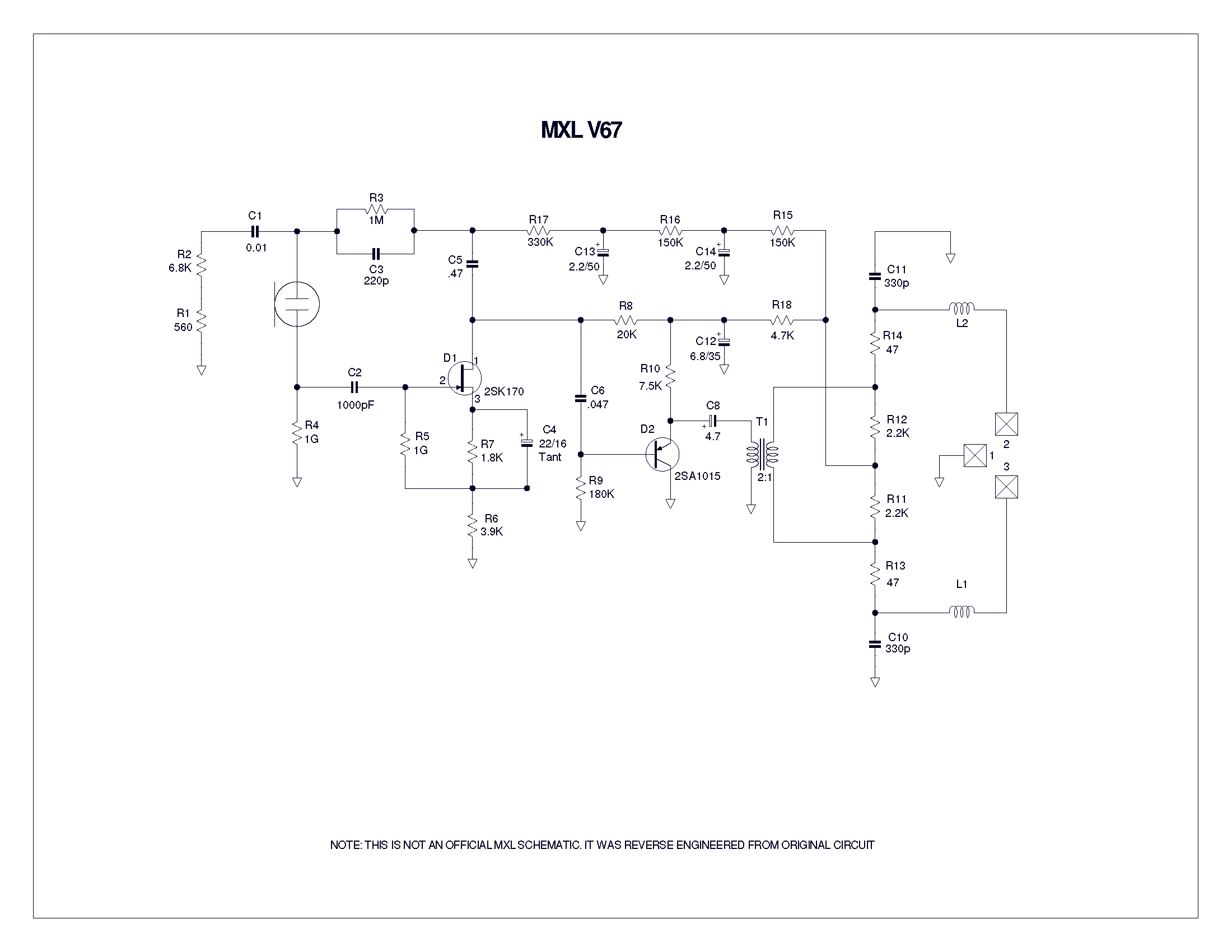
A user has been experimenting with modifications to a budget-friendly MXL V67s microphone to enhance its performance, specifically aiming to improve the condenser quality until a higher-end model can be acquired. The MXL V67s is a popular choice among budget-conscious...
Assistance is required regarding the circuits provided below. The focus is on an ultrasonic receiver circuit that utilizes two ultrasonic components. The ultrasonic receiver circuit is designed to detect ultrasonic waves, typically in the frequency range of 20 kHz to...
Warning: include(partials/cookie-banner.php): Failed to open stream: Permission denied in /var/www/html/nextgr/view-circuit.php on line 713
Warning: include(): Failed opening 'partials/cookie-banner.php' for inclusion (include_path='.:/usr/share/php') in /var/www/html/nextgr/view-circuit.php on line 713