
block diagram function generator

To explore basic theory and experimental circuit debugging techniques, this project employs an integrated operational amplifier and a differential amplifier to create a square wave, triangle wave, and sine wave generator. The generation process often begins with sine wave production, followed by shaping circuits that convert sine waves into square waves, and then using integration circuits to produce triangle waves. Alternatively, triangle waves can be generated first, which can then be transformed into sine or square waves.
The design focuses on generating square waves and triangle waves, which are subsequently converted into sine waves. This involves the use of a comparator and an integrator in the square-triangle wave generator circuit. The output square wave from the comparator is fed into the integrator to produce a triangular wave, while the transformation of the triangular wave into a sine wave is primarily achieved by the differential amplifier. The differential amplifier is characterized by a stable operating point, high input impedance, and strong resistance to interference, effectively suppressing DC amplifier zero drift and enabling the conversion of low-frequency triangle waves into sine waves. The wave transformation utilizes the nonlinear transfer characteristics of the differential amplifier.
The circuit design includes an inverting input hysteresis comparator and an RC circuit. The RC delay circuit serves dual purposes as part of the feedback network and as a timing element, allowing for automatic conversion of the output state through the charging and discharging of the capacitor. The output voltage is initially set at Uo = Uz, with the inverting input potential represented as Up = UT. The output voltage Uo is positively charged through resistor R3, leading to a gradual increase in the inverting input potential Un over time. As time progresses toward infinity, Un approaches Uz. When Un equals Ut, a slight increase causes Uo to jump from Uz to Uz, while Up similarly transitions from Ut to Ut. The output Uo then undergoes reverse charging through R3, resulting in a gradual decrease in Un over time until it approaches -Uz. When Un equals -Ut, Uo transitions from Uz to -Uz, and the capacitor begins to charge positively again. This cyclical process results in self-excited oscillation.
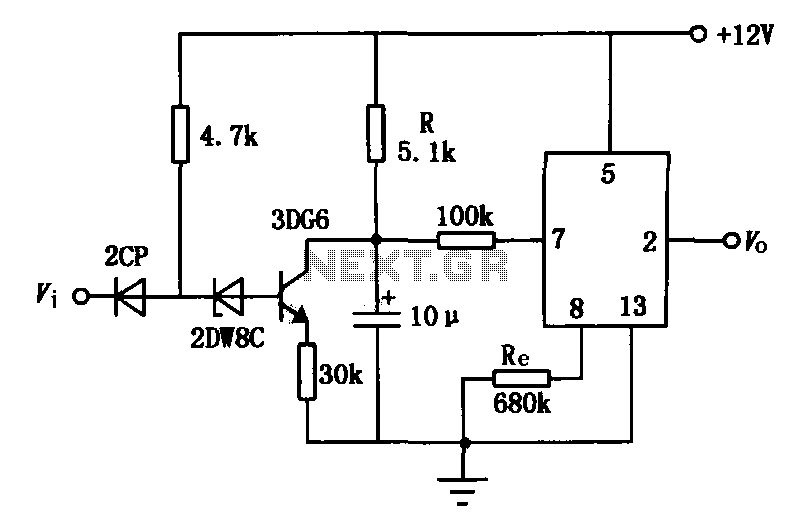
The square wave to triangle wave conversion circuit employs operational amplifier A1 in conjunction with resistors R1, R2, R3, and potentiometer RP1 to form a voltage comparator. Capacitor C1 is utilized to enhance the switching speed of the comparator. The inverting op-amp reference voltage is set to U- = 0, while the phase input voltage is denoted as Uia. Resistor R1 serves as a balance resistor. The comparator's output alternates between the high positive supply voltage Vcc and the low negative supply voltage -Vee. When the comparator's input U equals U- = 0, the operation continues to produce the desired waveforms.Function Generator Virtual Oscilloscope Sound card based multi-functional design, and virtual function generator Microcontroller based Function Generator Design and Implementation of graduation. The total program function generator Generally refers to the function generator automatically generates a sine wave, triangle wave, sawtooth affected parties, such as ladder wave voltage waveform of the circuit or equipment.
According to different purposes, there have three or more of the waveform function generator, using the device can be discrete devices (S101, such as low frequency signal function generator used in all transistors), integrated circuits can also be used (such as single function generator module 8038). To further understand the basic theory and experimental circuit debugging techniques, this project uses the integrated operational amplifier with differential amplifier composed of transistor square wave - Triangle wave - sine function generator design.
Generate sine, square, triangle There are many programs, such as the first sine wave generation, and then shaping circuit square wave sine transform, and then by the integration circuit becomes a square wave triangle wave; also produced the first triangle wave - square wave, triangle wave and then into a sine wave or square wave into a sine wave and so on. The subject of using the first generation square wave - the triangular wave, and then transform into a sine wave triangle wave circuit design, By the composition of the comparator and integrator square - triangle wave generator circuit, the comparator output of the square wave received by the integrator triangular wave, triangle wave to sine wave converter mainly by the differential amplifier to complete.
Differential amplifier with a stable operating point, high input impedance, the advantages of strong anti-interference ability. Especially as the DC amplifier zero drift can be suppressed effectively, it can be very low frequency triangle wave into a sine transform.
Wave Transformation is the use of differential amplifier nonlinear transfer characteristic. 2. The purpose of curriculum design and design task2. 1 Design Objective This circuit is the inverting input of hysteresis comparator and RC circuit. RC delay circuit, both as part of, but also as a feedback network, through the RC charging and discharging of the output state of the automatic conversion. The output voltage at a time set Uo = Uz, then inverting input potential Up = UT. Uo by R3 positive charge on the capacitor C, shown by the solid arrow. Inverting input of the potential growth of n with time t is gradually increased, when t goes to infinity, Un tend Uz; However, once the Un = Ut, and then slightly increased, Uo jump into from the Uz-Uz, and this Up from the same jump into Ut-Ut.
Then, Uo passed R3 reverse charging the capacitor C, as shown in the dotted line arrow. Un growth gradually reduced over time, when t approaches infinity, Un tend-Uz; However, once the Un =- Ut, then decreased, Uo-Uz jump into from the Uz, Up jumped into from-Ut Ut, began positively charged capacitor. The above process again and again, the circuit produced a self-excited oscillation. - 3. 2 square wave triangle wave converter works Square wave - triangular wave generator circuit If a point off, operation amplifier A1 and hair R1, R2 and R3, RP1 form voltage comparator, C1 to speed up the capacitor, the switching speed comparator.
Inverting op amp reference voltage termination, the U-= 0, with phase input termination voltage Uia, R1 is called balance of resistance. The output of the comparator is equal to the high Uo1 positive supply voltage Vcc, low level equal to the negative supply voltage-Vee (), When the comparator U = U-= 0, the com
🔗 External reference
Related Circuits
The circuit is based on four integrated circuits: TL072, TL074, MN3101, and MN3004, which produce four output channels for surround audio, specifically targeting center, rear, front right, and front left audio. It is a compact amplifier capable of delivering...
Police siren circuit diagram. This circuit produces a sound similar to a police siren. It utilizes two 555 timer ICs. The police siren circuit typically employs two 555 timer integrated circuits (ICs) configured in astable mode to generate a square...
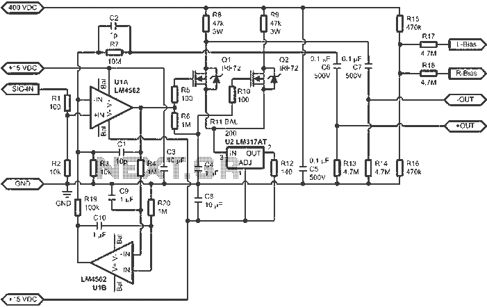
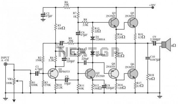
When connected to popular Stax Class 1 electrostatic headphones, the design illustrated in the figures may operate across the full audio bandwidth with a transmission voltage close to 200 Vp-p. Although the resistor divider can be modified to provide...
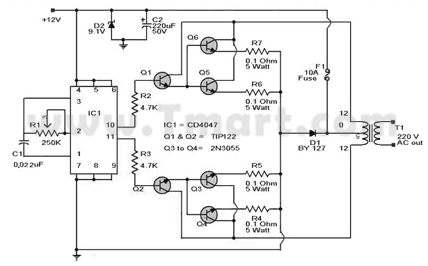
A durable car power inverter enhances convenience for users. A 100W car power inverter is an optimal choice for travelers while driving or during urgent power outages. This AC adapter is compatible with various electrical devices rated for AC...
The delay application circuit is depicted in Figure JEC-2, which consists of two components. When the input transitions from logic level 0 to 1, the output also changes to 1 immediately. However, when the input transitions from high level...
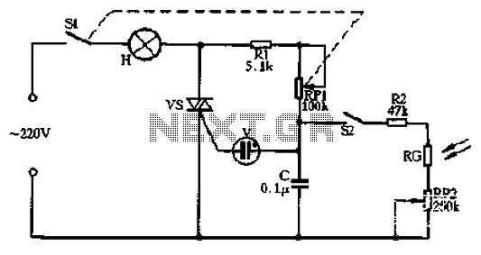
Circle S2 is a stable automatic light switch. When S2 is open, the entire circuit operates as a subsection II SCR stepless presentation dimmer, omitting the high-frequency filter circuit. The trigger diode switch activates a neon indicator bulb (V),...