
Stepless triac dimmer with a steady light function
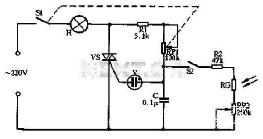
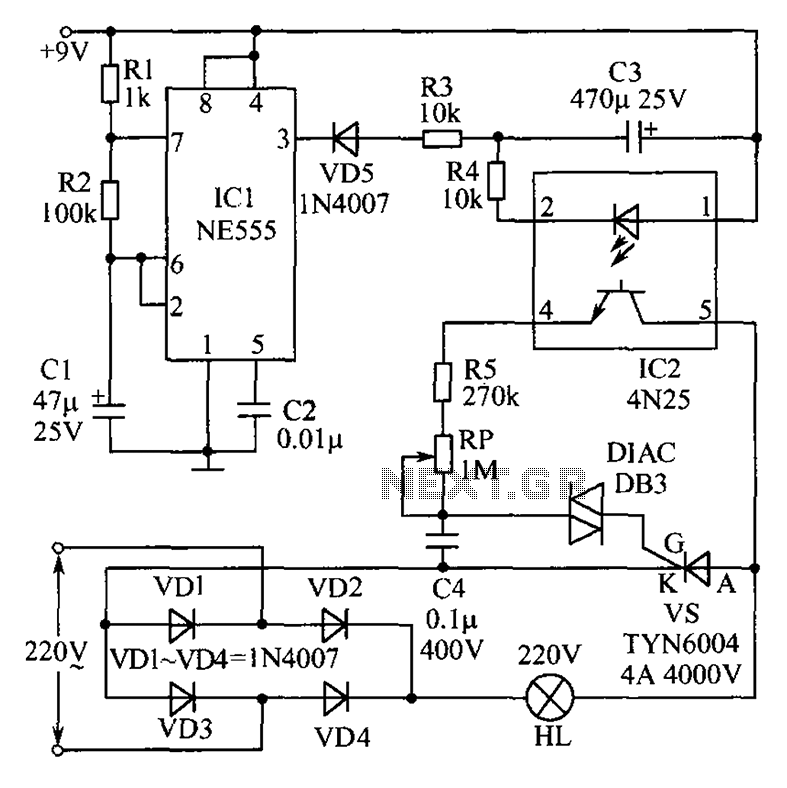
The circuit design described involves an automatic light switch (S2) that integrates a silicon-controlled rectifier (SCR) dimmer for smooth brightness control. When S2 is in the open position, the circuit functions as a dimmer, allowing for fine-tuning of the lamp's brightness through the potentiometer (RP1). The omission of the high-frequency filter circuit indicates a focus on simplicity and reliability in the circuit's operation.
The neon bulb (V) serves a dual purpose: it acts as an indicator light when the circuit is in dimming mode, illuminating with a red glow to signal the user. The functionality of the circuit is further enhanced by the use of a photoresistor (RG), which automatically adjusts the charging rate of the capacitor (C) based on the ambient light conditions. This feature ensures that the lamp (H) provides adequate illumination regardless of external lighting, enhancing the circuit's adaptability.
The interplay between the resistances (R2, RP2, RG) and the capacitance (C) creates a dynamic response to changing light conditions. In bright environments, the photoresistor's decreased resistance leads to a slower charge rate for the capacitor (C), thus reducing the brightness of the lamp (H). In contrast, in dim environments, the increased charge rate results in a brighter output from the lamp (H). This feedback mechanism allows the circuit to maintain a consistent level of illumination, fulfilling its purpose as a stable automatic light switch.
Overall, the design emphasizes user convenience, energy efficiency, and adaptability to varying light conditions, making it a practical solution for automatic lighting applications. Circle S2 is stable automatic light switch, when S2 is open, the entire circuit is Subsection II SCR stepless presentation dimmer, simply omit the high-frequency filter circuit , and the trigger diode switch neon bubble V, adjust potentiometer RP1 may vary depending on the brightness of the lamp is seeking to adjust the heart H, then V can emit red neon glow bubble, can serve as indicator role, this time electric road do not have stable light function. Automatically when needed steady light, you can press the switch S2, at this time the resistance (R2 + RP2 + RG) and capacitance C in parallel with it (RI + RP1) together determine the charging rate of the capacitor C.
Charge rate on the one hand by the capacitance C (Rl + RPl) decision, so the resistance is still described as adjusting brightness RPI section H of the lamp; charging rate of capacitor C and by (R2 + RP2 + RG) branch influence, which is RG photoresistor, which changes the size of the resistance by the ambient light intensity changes, when the ambient illuminance is high, RO resistance was low, so the capacitor C charge rate slows down, vs SCR conduction angle becomes small, light H hair brightness is reduced if the ambient illumination is gradually reduced, the slip streaming effect is reduced, so the capacitor C charging rate of speed, vs SCR conduction angle is gradually increased, the brightness of the lamp H also will be increased in order to ensure the illuminated face in light of the stable and unchanging purpose.
Related Circuits

This circuit is straightforward yet valuable, providing a high-quality interior light delay feature. This feature is standard in most modern vehicles, though the automatic dimming version is typically found in higher-end models. This circuit allows for the enhancement of...
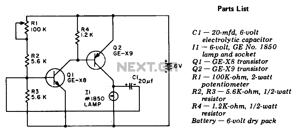
The circuit is a two-stage, direct-coupled transistor amplifier configured as a free-running multivibrator. Both the flash duration and flash interval can be adjusted by turning the potentiometer, R1. The described circuit operates as a two-stage, direct-coupled transistor amplifier, functioning as...
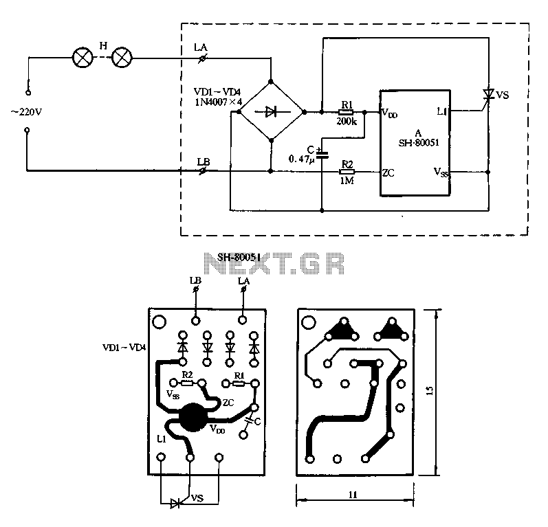
Figure 2-85 illustrates a single-channel SH-80051 flash controller. The SH-80051 chip features four terminals: the positive power supply terminal (VDD), the synchronization input (zc), the negative power supply terminal (VSS), and the drive output (L1). The chip operates with...
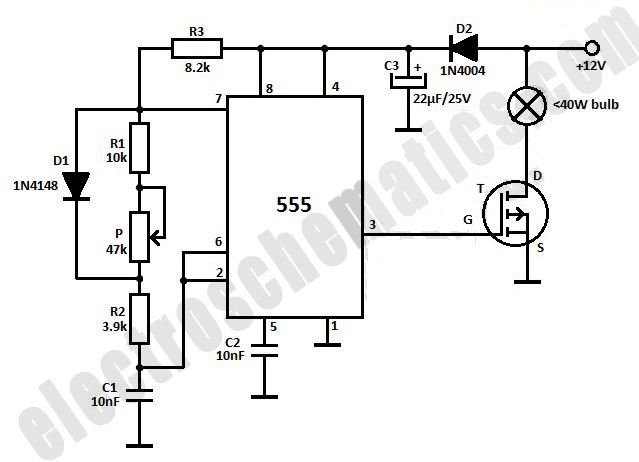
This light dimmer is designed to adjust the brightness of 12V light bulbs utilizing the widely recognized 555 timer, which is configured as an astable multivibrator. The pulses generated by the timer control the power delivered to the light...
This circuit features an appealing Christmas lights setup. Upon activation, the lights (HL) gradually increase in brightness. Once they reach maximum brightness, they automatically dim, and upon reaching the lowest brightness, they gradually brighten again, creating a smooth transition...
The circuit consists of two building blocks. The first is a square wave oscillator made up of two transistors in a multivibrator arrangement and the second is a CD 4017 decade counter IC. The multivibrator contains two extra components...
Warning: include(partials/cookie-banner.php): Failed to open stream: Permission denied in /var/www/html/nextgr/view-circuit.php on line 713
Warning: include(): Failed opening 'partials/cookie-banner.php' for inclusion (include_path='.:/usr/share/php') in /var/www/html/nextgr/view-circuit.php on line 713