
Bonsai electronic circuit

The circuit described utilizes two pairs of D flip-flops (CD4013), which serve as the primary control elements for the LED flashing effect. The D flip-flops are configured to toggle states based on clock inputs, creating a sequential output that drives the LEDs. The choice of VT 9013 transistors ensures that the circuit can handle the required current for the LEDs while maintaining a suitable switching speed due to their beta rating of 90.
The LEDs, while selected for their visual impact, can vary in color, contributing to a dynamic display. In cases where a higher brightness or more extensive LED array is desired, the use of larger transistors like the 8050 or DD01 is recommended to accommodate the increased current demands. The resistors (R10 to R14) at 470 ohms provide current limiting for the LEDs, ensuring that they operate within safe limits and prolong their lifespan.
Capacitors C1 to C8, rated at 1000 µF/16V, are employed to smooth out any voltage fluctuations in the circuit, providing stability to the operation of the flip-flops and preventing flickering of the LEDs. The touch-type power switch (CS-316) allows for easy activation and deactivation of the circuit, enhancing user convenience.
Lastly, the transformer rated at 220V/10V, 5W is responsible for stepping down the mains voltage to a suitable level for the circuit, ensuring safe operation. This design not only serves a functional purpose but also adds aesthetic value to the living space, making it an ideal choice for decorative lighting applications. As shown for the electronic components made by conventional electronic bonsai, on the living room, sparkle, brilliance make houseful, joys and pleasures of life. Components Sel ection: IC1 ~ IC4 are two pairs of D flip-flop CD4013; all the transistors are selected VT 9013 and other NPN silicon transistor, beta 90. LED models informal, in pursuit of flash effect, even if the same group of five LED is not necessarily a color.
As the number of too little LED, can be increased, but slightly larger transistors are required to use, such as 8050, DD01 and the like. R10 ~ R14 choose 470 Omega resistance. C1 ~ C8 selection 1001 mu F/16V electrolytic capacitor. S for small touch-type power switch CS-316. T use 220V/10V, 5W of small power transformers.
Related Circuits
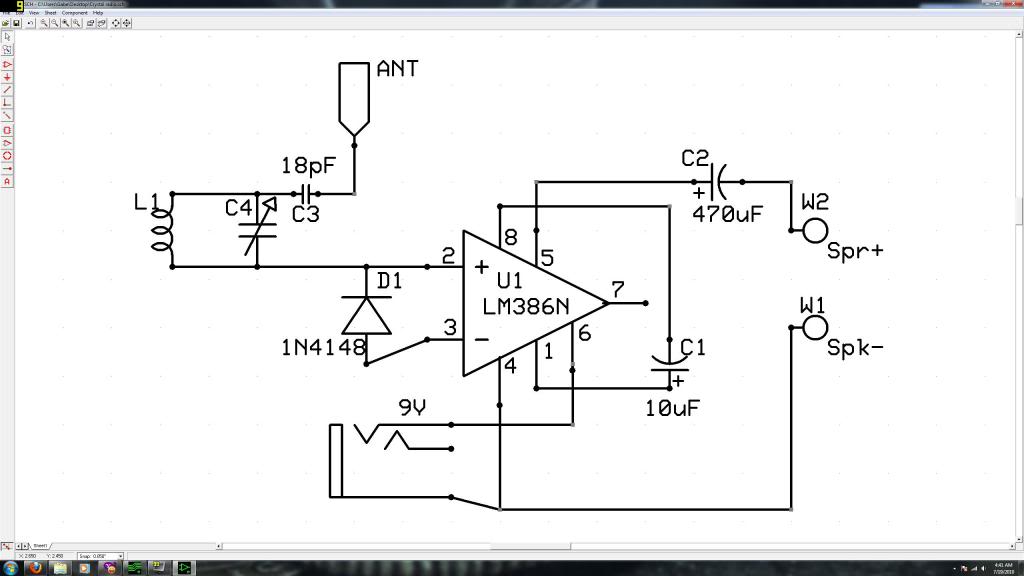
Initially, the individual has limited experience in electronics. They constructed a crystal radio circuit using components salvaged from a non-functional radio, including an LM386N audio amplifier. A crystal radio circuit is a simple radio receiver that operates without the need...
The tank circuit consisting of capacitor C2 and inductor L1 is utilized to tune the transmitter. The antenna is coupled to the transmitter through capacitor C3 and can be either a telescopic antenna or a length of hookup wire....
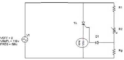
Simple resistor and diode combinations are used to trigger and control silicon-controlled rectifiers (SCRs) across the full 180-degree electrical range, exhibiting reliable performance at commercial temperatures. These circuits function optimally when SCRs possess relatively high gate sensitivities. In this...

This second-order filter, designed for audio applications, utilizes an LM1458 or a similar operational amplifier. It is tunable with a cutoff frequency ranging from 30 Hz to 300 Hz. The resistors R2a and R2b are ganged log-taper potentiometers. The described...

This circuit was utilized with an audio power amplifier to identify the point at which the output is -3 dB from maximum, indicated by LED D5, and at clipping, shown by LED D6. The indicator can be employed with...
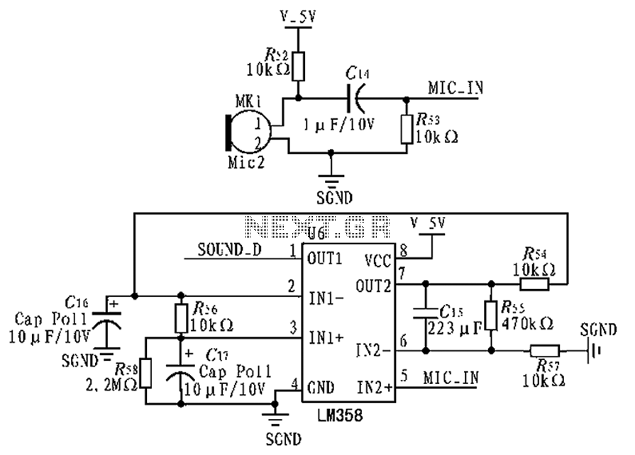
The circuit diagram focuses on the research and design features applied to mobile robots. The design considers small size, low power consumption, and ease of movement, catering to home users with a user-friendly display interface. For speech recognition, a...