
Bridge the digital pressure signal conditioner MAX1458 excitation circuit diagram

The excitation circuit of the MAX1458 digital pressure signal conditioner is designed to facilitate precision control of the excitation current supplied to the sensor. The architecture includes a digital-to-analog converter (DAC3), which plays a critical role in modulating the sensor excitation current (IBR) to achieve accurate calibration across the full scale. The reference current (IISRC) is established by the resistor RISRC, with the voltage at pin 9 influencing its value.
The current mirror configuration, comprising V1 and V2, is engineered to amplify the reference current by a factor of 14, thereby allowing the excitation current IBR to be programmed within a specified range of 0.1 mA to 2 mA. This capability is essential for adapting the excitation current to the specific requirements of various sensor applications, ensuring optimal performance.
The circuit employs analog switches S1 and S2, which are controlled through configuration registers, enabling selective activation of the excitation current path. This flexibility is crucial for dynamic system adjustments and operational efficiency.
Furthermore, the compensation mechanism for variations in full-scale output voltage is integrated within DAC3. As the output voltage fluctuates, DAC3 adjusts the output voltage (BR) accordingly, effectively correcting any full-scale errors that may arise. This feedback loop enhances the accuracy of the pressure measurement system.
Additionally, DAC4 is incorporated to address temperature-related errors in the full-scale output. By compensating for the temperature coefficient, DAC4 ensures that the system maintains its accuracy across varying thermal conditions, further solidifying the reliability of the MAX1458 digital pressure signal conditioner in diverse applications. Bridge the digital pressure signal conditioner MAX1458 excitation circuit is shown. Using the output DAC3 to change the size of the sensor excitation current IBR, you can achie ve full-scale fine calibration. IISRC reference current by RISRC and 9-pin voltage is set. V1 and V2 composed of current mirror, the current gain of 14 times, allow the excitation current IBR 14IISRC. IBR programming range is 0.1 ~ 2mA. Analog switches S1, S2 on-off state governed by the configuration registers. Obviously, when the full-scale output voltage changes, DAC3 bridge will be compensated by changing the output voltage, BR, thereby correcting the full-scale error.
DAC4 full scale temperature coefficient for correcting errors.
Related Circuits
This room light controller project automatically uses a microcontroller to manage a visitor counter, providing a reliable circuit for controlling the room lighting. The room light controller circuit integrates a microcontroller that processes inputs from a visitor counter. This setup...

This is a white LED lamp that activates when the telephone rings. The cool white light aids in locating the phone in low-light conditions and assists in managing clutter. The circuit for the white LED lamp that illuminates upon a...
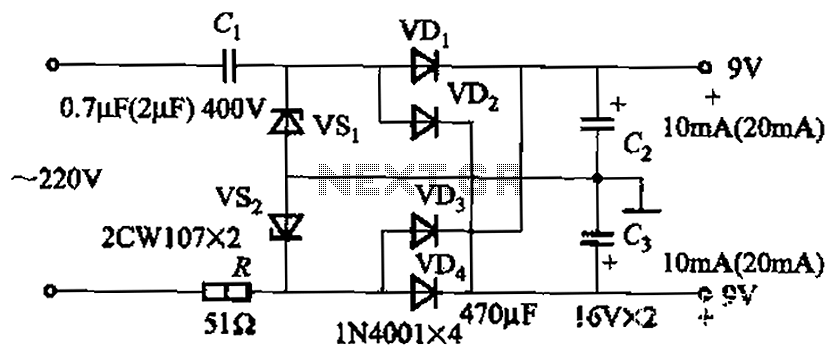
The circuit's output current capacity is influenced by the bulk capacitor Cl. When the capacitance of Cl is changed from 0.7 µF to 2 pF, the output current can be increased from approximately 10 mA to around 20 mA,...
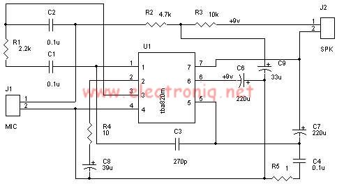
A very simple audio amplifier circuit can be designed using the TBA820M audio amplifier integrated circuit with just a few electronic components. This audio amplifier project features a high gain that allows for the detection of sounds underwater. The...
The minimum voltage required for this circuit is 8 volts, while the maximum voltage is 28 volts. It can be used to amplify audio signals in electronic devices such as radios, DVDs, MP4 players, and MP5 players. The circuit...

This is a design circuit diagram of a versatile FM transmitter. This circuit does not include a coil and is simple and easy to assemble. It operates based on gate logic concepts. The circuit features a buffer gate N1...