
BT136 Temperature Controlled Fan Regulator
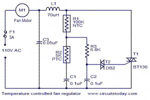
This circuit is designed to automatically adjust the speed of a fan based on the ambient temperature. It utilizes several key components, including a BT136 Triac, which serves as the main switching element, allowing for control of the fan motor's power supply.
The system begins with a temperature sensor that monitors the surrounding environment. As the temperature rises, the sensor outputs a corresponding voltage signal. This signal is fed into a control circuit that includes a resistor and capacitor, forming an RC network that helps to filter and stabilize the input signal.
The BT136 Triac is triggered by the control circuit when the temperature exceeds a predetermined threshold. This component is capable of handling AC loads, making it suitable for controlling the fan motor directly. The Triac effectively modulates the voltage supplied to the fan, enabling speed control through phase angle modulation.
A relay may also be incorporated into the design to provide isolation between the control circuit and the high-power fan motor. This ensures that the sensitive components are protected from high voltage spikes that can occur during operation.
The fan motor receives power from the AC supply, and its speed is adjusted based on the current flowing through the Triac, which is influenced by the temperature readings. By incorporating these components into a cohesive circuit, the system can efficiently maintain comfortable temperature levels within a designated space while optimizing energy consumption.
Overall, this automated fan speed control circuit is an effective solution for temperature regulation, enhancing both comfort and energy efficiency in various applications.The function for automatically control the speed of your fan according to the temperature.? Component: BT136 Triac, Capacitor, Resistor, Relay, Fan Motor, . 🔗 External reference
Related Circuits
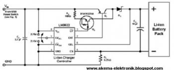
The following circuit illustrates a simple battery charger equipped with a temperature sensor. This circuit is based on the LM350 integrated circuit. Features include negative... The circuit utilizes the LM350 voltage regulator IC, which is known for its ability to...
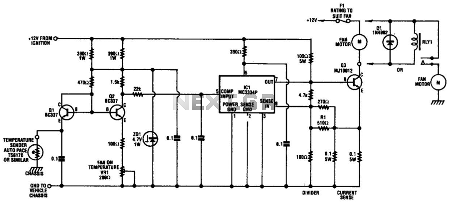
The circuit is based on a commercial temperature sensor (TS6178) and an MC3334P ignition chip. When the radiator temperature increases, the sensor pulls the base of Q2 low via Q1, which is wired as a diode. Q2's collector thus...
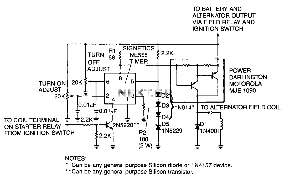
A monolithic 555-type timer serves as the core component of this straightforward automobile voltage regulator. When the timer is inactive, resulting in a low output at pin 3, the power Darlington transistor pair remains off. If the battery voltage...

When discussing fan control, there are generally two methods: linear control and pulse-width modulation (PWM) control. Linear control is the most commonly used method, which involves reducing the voltage supplied to the fan. For a fan rated at 12...
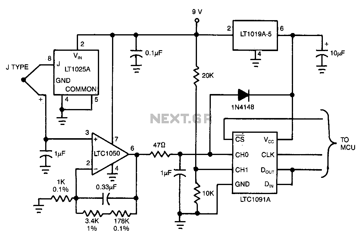
This circuit is designed to measure the exhaust gas temperature in a furnace. The 10-bit LTC1091A provides a resolution of 0.5°C over a temperature range of 0°C to 500°C. The LTC1050 amplifies and filters the thermocouple signal, while the...
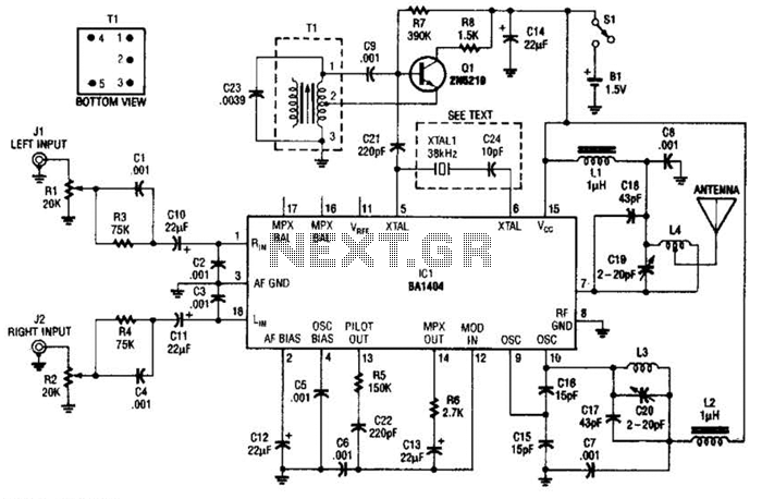
In this application, a BA1404 is utilized to generate an FM MPX baseband signal. This signal modulates a crystal oscillator (Q3) through a dual varactor series modulator. This transmitter can be used to play CD audio on an existing...
Warning: include(partials/cookie-banner.php): Failed to open stream: Permission denied in /var/www/html/nextgr/view-circuit.php on line 713
Warning: include(): Failed opening 'partials/cookie-banner.php' for inclusion (include_path='.:/usr/share/php') in /var/www/html/nextgr/view-circuit.php on line 713