
8 Channel software controlled fanbus with PWM

A Vero board utilizes horizontal copper tracks that are interconnected, allowing for the construction of smaller circuits. This method is relatively straightforward but requires patience and is best suited for experienced hobbyists. Alternatively, a PCB pen can be used to draw insulating tracks on raw copper plates, followed by etching the exposed copper. While this method is accessible, it demands a steady hand and can yield variable results in terms of aesthetics. Another approach, known as photo printing, offers industry-quality results. This method involves exposing a photosensitive copper plate to UV light, using a transparent paper mask for the layout, followed by developing and etching processes. Although it is more costly, it produces superior quality PCBs. For this project, a PCB has been designed with pre-drilled holes, intended for mounting on the back of a 5.25-inch front bezel. This PCB is available for purchase, providing a convenient solution for those who prefer not to engage in etching or manual drawing. Contact information for purchasing is available on the last page.When speaking of fan control, there are generally 2 ways of doing it, linear control, and pulse-width control. The linear control is the most common. The idea is to decrease the voltage to the fan. If the fan is specified to 12 volts, in most cases you can lower the voltage to 6-7 volts. But if you want to go lower, the result is often that your f ans won`t even start. Another issue is step less regulation. This requires a variable resistor (rheostat) or a control circuit, using transistors. If you want to run a fan at 7 volts, the remaining 5 volts will have to be burned of as heat in the control circuit or rheostat. The linear control supplies the fan with a constant voltage. But the PWM control generates rapid 12 volt pulses, and the on and off timing determines the overall speed of the fans.
Until now, the construction of a PWM circuit has been pretty tricky. It requires an advanced circuit to control the different time constants. But with CKControl II, all timing signals are controlled via the software, allowing us to utilize the PC parallel port as 8 individual, fully controllable PWM outputs. You can use the outputs for not only fans, but all kinds of things including Lazer LED`s, Cold Cathode lights as long as the maximum current output doesn`t exceed 0, 8 A for each channel.
You could even add a relay and make the software turn your coffee machine on and off! How many fans can we add to the circuit, then That depends on the fans used. The electronic components used are specified to 1 Ampere per channel. With that in mind, we should stay below 0, 8 Ampere, or approx. 10 Watt per channel. A standard 80mm fan typically uses 0, 14 0, 18 mA (1 mA = 1/1000 Ampere). That makes 5 fans per channel a total of 40 fans for all 8 channels. But that`s a rather theoretical value; as 40 fans would demand a heavy duty power supply, as well as thick wires and PCB tracks. In addition, considerably few of us uses 40 fans in our desktop computers. You can`t use this circuit to control your CPU or GPU cooler. To increase stability, the fans won`t start running until Windows is loaded and CKControl II is initialised.
1) A so-called Vero board uses horizontal copper tracks, tied together. This makes you able to build smaller constructions, fairly easy, but it takes a certain amount of patience, and is only suitable if you are an experienced hobby-electronics builder. 2) By means of a PCB-pen, it is possible to literally draw insulating tracks on raw copper-plates, and then etch the remaining naked copper away.
It`s an easy way of creating PCB`s, but even with a steady hand, the overall outcome may not look so nice. It also takes some technique and experience to draw a circuit like this by hand. 3) Another method called photo print, gives you industry like quality. It is done by exposing a photosensitive copperplate to UV-light, masking the layout with a transparent paper copy, and then applying developing fluids and finally etching.
It`s quite expensive, but also gives you the finest results. 4) For this project, we have constructed a PCB with the holes already drilled. The PCB is designed to be mounted on the backside of a 5, 25 front bezel. The PCB can be bought from us, and is an easy solution if you`re not into etching and drawing yourself. See the contact info on the last page. 🔗 External reference
Related Circuits
This circuit is designed to connect stereo outputs from four different sources or channels as inputs, allowing only one of them to be selected and connected to the output at any given time. When the power supply is turned...
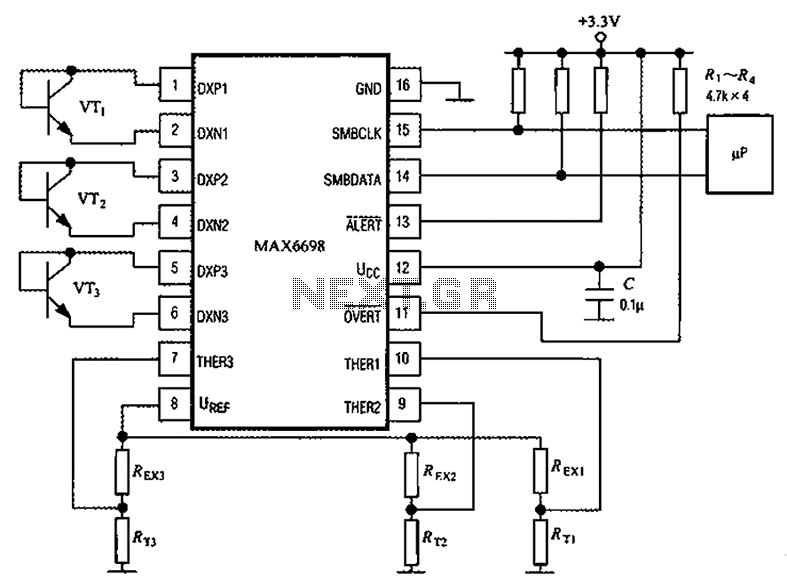
Channel 7 presents a circuit diagram of a smart temperature sensor using the MAX6698. This circuit includes three transistors (VT1, VT2, and VT3) and three thermistors (RT1, RT2, and RT3). An internal reference voltage source is provided via resistors...
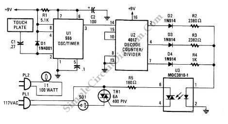
This is a three-mode lamp dimmer circuit with touch control. This circuit can be used to control a lamp in three operation modes: dim, off, and bright. It utilizes a NE555 timer. The three-mode lamp dimmer circuit designed with touch...
The RF engineer occasionally needs to find an instrument that can reliably and quickly test a low-frequency quartz crystal unit. This equipment is often challenging to locate, leading engineers to consult electronic circuits handbooks for schematics that can perform...
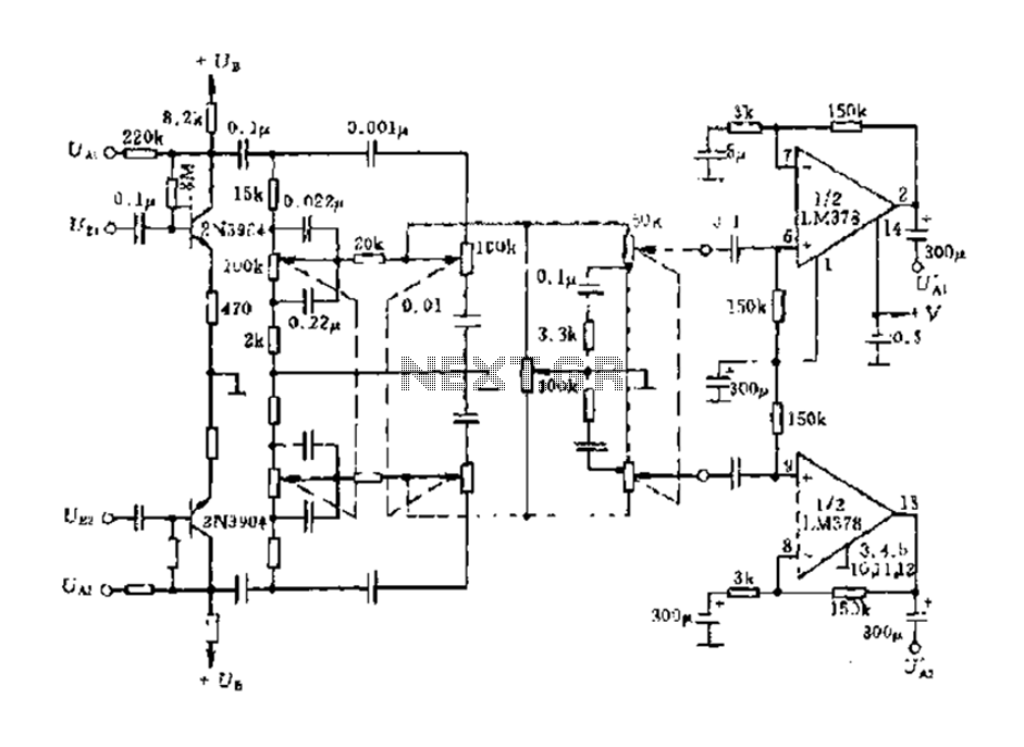
The dual-channel circuit features the LM378 dual operational amplifier and operates with a supply voltage of 24V, supporting an 8-ohm load (or 16 ohms). Each channel delivers an output power of 4W. The circuit includes internal current limiting and...
The circuit is designed to provide two channels on a stereo mixer intended for microphones, incorporating a crossfader operation. It utilizes the NE5532 integrated circuit. The stereo mixer circuit features two independent channels, each capable of handling microphone input signals....