
Build A 10 Amp 13.8 Volt Power Supply
The process of designing and constructing a home-brew power supply involves several key components and considerations. A typical schematic for a linear power supply might include the following elements:
1. **Transformer**: The transformer is the heart of the power supply, stepping down high voltage AC mains to a lower AC voltage suitable for the application. A toroidal transformer is often preferred for its compact size and efficiency. The voltage rating should match the required output voltage, while the current rating should exceed the maximum load current.
2. **Rectifier**: After the transformer, a rectifier circuit is used to convert the AC voltage to DC. A full-wave bridge rectifier configuration is commonly employed for better efficiency and reduced ripple voltage. This consists of four diodes arranged in a bridge configuration, allowing both halves of the AC waveform to contribute to the output.
3. **Filtering**: Following rectification, a filter capacitor is used to smooth the pulsating DC voltage. The capacitance value should be chosen based on the load current and acceptable ripple voltage. Larger capacitors will reduce ripple but will also increase the inrush current during power-up, which may require additional considerations for surge protection.
4. **Voltage Regulation**: To maintain a stable output voltage under varying load conditions, a linear voltage regulator may be incorporated. Common choices include the LM7812 for +12V outputs or LM317 for adjustable outputs. The regulator will require input and output capacitors to ensure stability and transient response.
5. **Protection Circuitry**: Fuses or circuit breakers should be included to protect against overcurrent conditions. Additionally, incorporating a thermal shutdown feature can prevent damage due to overheating.
6. **Heat Sinking**: Power components, especially regulators, will generate heat. Adequate heat sinking is necessary to dissipate this heat and maintain reliable operation. The heat sink should be sized based on the power dissipation of the components and the ambient temperature.
7. **Output Connections**: Finally, the schematic should include output connectors that are suitable for the intended application, ensuring that they can handle the voltage and current requirements.
When designing a home-brew power supply, attention must be paid to safety considerations, including proper insulation, grounding, and adherence to local electrical codes. The layout of the components on the PCB or breadboard should minimize noise and interference, ensuring a clean power output suitable for sensitive electronics like radio equipment.Sometimes amateurs like to home-brew their power supplies instead of purchasing one off the shelf at any of the major ham radio retail dealers. The advantage to rolling your own power supply is that it teaches us how they work and makes it easier to troubleshoot and repair other power supply units in the shack.
It should be noted that there is no real cost advantage to building your own power supply unless you can get a large power transformer and heat sink for a super low price. 🔗 External reference
Related Circuits
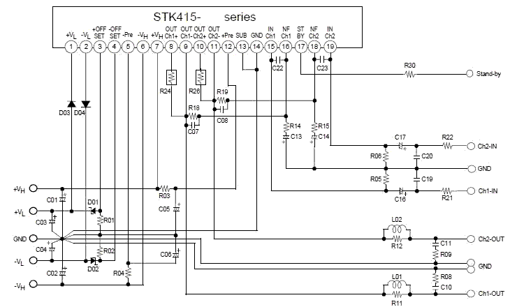
This electronic project stereo amp is based on the STK415-090-E class H audio power amplifier hybrid IC that features a built-in power supply switching circuit. This STK415-090-E class H audio power amplifier provides high efficiency audio power amplification by...
This simple amplifier is ideal for adding a headphone jack to equipment that lacks this feature. The Headphone Buffer circuit board is small enough (1.2" X 1.4") to squeeze into even the smallest spaces and power requirements are so...
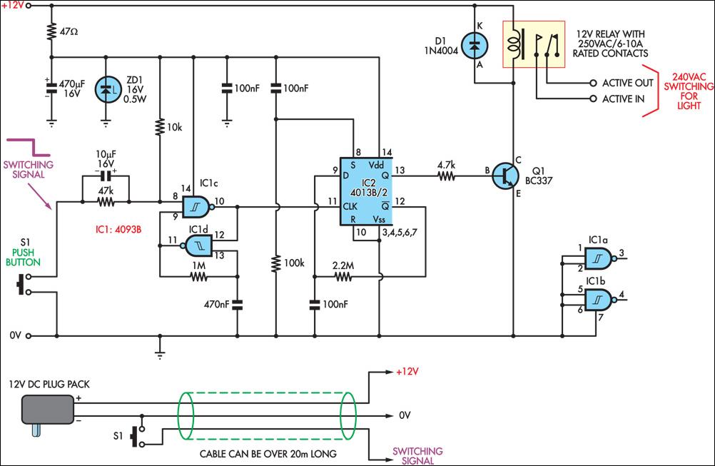
This circuit enables the remote control of a 240V mains appliance, such as a light bulb, through low-voltage cabling and a pushbutton switch. The mains appliance is activated using a suitably-rated relay. All electronic components are housed in an...
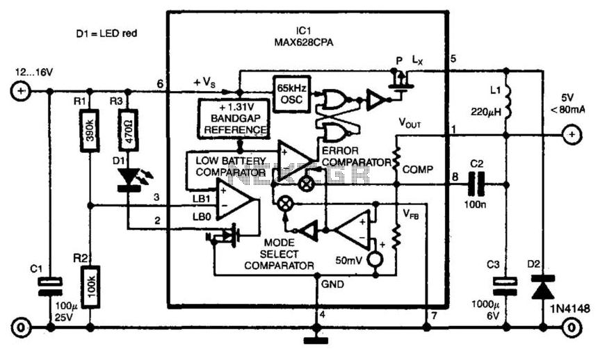
Switch-mode power supplies offer significantly greater efficiency compared to traditional power supplies. The switch-mode regulator described here achieves an efficiency of approximately 85%. It converts an input voltage range of 12 to 16 VDC into a stable output voltage...
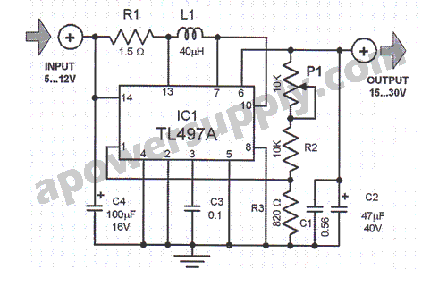
This voltage converter is constructed using the TL497A integrated circuit and is designed to convert an input voltage range of 5 to 12 volts into a higher output voltage range of 15 to 30 volts. This functionality is particularly...
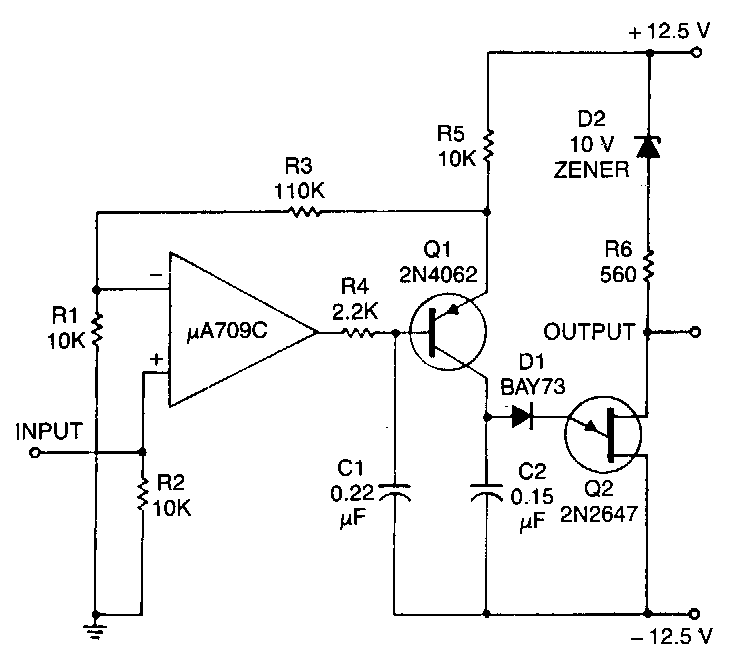
This circuit consists of a UJT oscillator in which the timing charge capacitor C2 is linearly dependent on the input signal voltage. The charging current is set by the voltage across resistor R5, which is accurately controlled by the...
Warning: include(partials/cookie-banner.php): Failed to open stream: Permission denied in /var/www/html/nextgr/view-circuit.php on line 713
Warning: include(): Failed opening 'partials/cookie-banner.php' for inclusion (include_path='.:/usr/share/php') in /var/www/html/nextgr/view-circuit.php on line 713