
Voltage to-frequency-converter
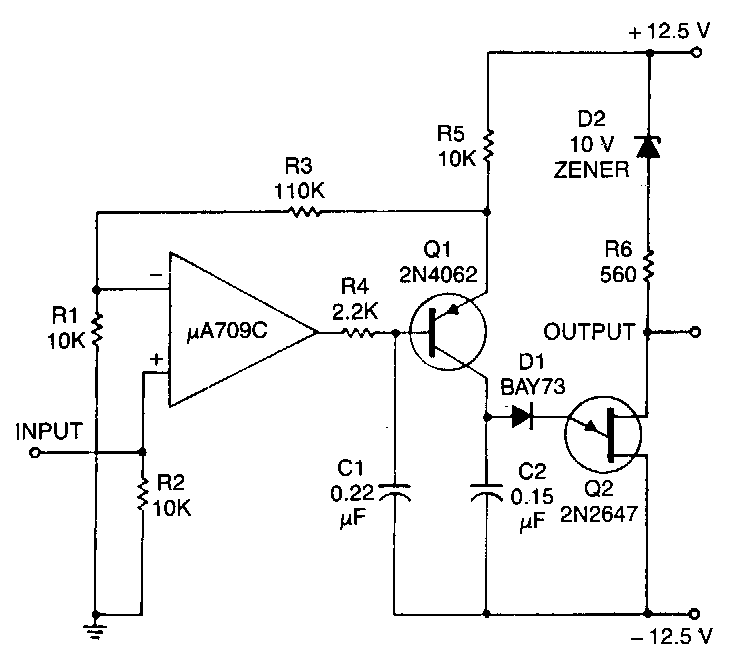
The described circuit is a Unijunction Transistor (UJT) oscillator, a type of relaxation oscillator known for its simplicity and effectiveness in generating pulse signals. The UJT operates based on the principle of negative resistance, allowing it to produce oscillations when connected to a charging capacitor and a resistor network.
In this configuration, capacitor C2 plays a crucial role as the timing element. Its charge time is directly influenced by the input signal voltage, which provides a variable timing characteristic. As the input voltage increases, the charging current flowing through resistor R5 also increases, leading to a faster charge time for C2. Conversely, a lower input voltage results in a slower charge time, creating a direct relationship between the input signal and the output frequency of the oscillator.
Resistor R5 is strategically placed in the circuit to regulate the charging current. The voltage across R5 is monitored and controlled by an amplifier, ensuring that the charging process remains stable and predictable. This feedback mechanism allows for precise control over the oscillation frequency and output signal characteristics, making the circuit suitable for various applications such as timers, pulse generators, and frequency modulation.
The UJT oscillator's output can be further refined by integrating additional components, such as filters or amplifiers, depending on the desired application. Overall, this circuit exemplifies a practical approach to generating oscillatory signals with adjustable frequency based on input conditions.This circuit consists of a UJT oscillator in which the timing charge capacitor C2 is linearly dependent on the input sigoal voltage. The charging current is set by the voltage across resistor R5. which is accurately controlled by the amplifier 🔗 External reference
Related Circuits

This circuit is a voltage-controlled oscillator (VCO) that utilizes the 555 timer integrated circuit (IC) as its primary component. The 555 timer is configured as an astable multivibrator, enabling it to function as an oscillator. An astable multivibrator is...

AVR has two different programming modes called Parallel Programming Mode (Parallel Mode) and Serial Downloading Mode (ISP mode). In Parallel Mode, the programming is done using multiple data lines simultaneously, allowing for faster programming speeds. This mode is typically...
If you have ever wanted a high-voltage generator to create impressive lightning effects, conduct Kirlian photography experiments, or experiment with neon lights, this project is ideal. It describes a laboratory pulse generator utilizing an auto-ignition coil, capable of delivering...
Until Willow Garage was acquired, there was work as a Web Robotics Engineer. This title reflects a role as a full-stack engineer focused on real-time, distributed robot control. Notable projects include an XML-RPC server and client for Node.js, a...
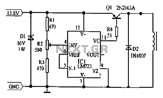
Cars are equipped with a circuit that includes an LM723 regulator, which can serve as a replacement for traditional automobile generator systems that utilize electromechanical charging regulators. This circuit offers superior performance compared to conventional systems. It ensures that...

This voltage booster circuit for driving one or more white LEDs utilizes a 555 timer as its main component. The timer, designated as IC1, operates as a resettable astable multivibrator with R1, R2, and C2 serving as the timing...
Warning: include(partials/cookie-banner.php): Failed to open stream: Permission denied in /var/www/html/nextgr/view-circuit.php on line 713
Warning: include(): Failed opening 'partials/cookie-banner.php' for inclusion (include_path='.:/usr/share/php') in /var/www/html/nextgr/view-circuit.php on line 713