
Build A Simple Twin Tee Phase Shift Audio Oscillator and Audio Amplifier
The twin "T" phase shift oscillator is a classic electronic circuit used to generate audio frequencies. The circuit typically consists of a transistor, which acts as the main amplifying component, and a phase-shifting network that includes resistors and capacitors. The twin "T" network is specifically designed to provide the necessary phase shift for positive feedback, which is essential for sustained oscillation.
In this circuit, the phase shift network is configured to achieve a total phase shift of 360 degrees, which corresponds to a complete cycle of oscillation. The unique arrangement of resistors and capacitors allows for precise control over the oscillation frequency, making it suitable for various audio applications. The frequency of the oscillator can be adjusted by changing the values of the resistors and capacitors in the phase shift network.
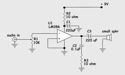
The LM386 audio amplifier IC is an ideal choice for this application due to its low power consumption and ability to drive small speakers effectively. The IC operates at a low voltage, making it suitable for battery-powered applications. The internal architecture of the LM386 includes a gain of 20, which can be increased to 200 through the addition of external resistors and capacitors, thus providing flexibility in output power.
When assembling the circuit, it is essential to maintain a clean layout to minimize noise and interference. Short connections help reduce parasitic capacitance and inductance, which can adversely affect the performance of the oscillator. Proper grounding is critical; all grounds should be connected to a common point to prevent ground loops and ensure stable operation.
Overall, the twin "T" phase shift oscillator combined with the LM386 audio amplifier forms a simple yet effective audio generation system suitable for educational purposes, hobby projects, and experimentation in audio electronics.Above is a schematic diagram of a type of audio oscillator known as a twin "T" phase shift oscillator. It gets its name from the phase shift network made up of R3, R4 and C3 plus C1, C2 and R2 which shifts the phase of the signal fed back from the collector to the base by 180 degrees for the feedback to make the oscillator oscillate.
You will noti ce that the emitter of Q1 is not connected. Bringing this connection to ground will turn on the oscillator or "key it" as it`s called. You could connect this to a telegraph key and make a code practice oscillator. Now we need to be able to connect a speaker to it so we can hear the tone. To do this we need an audio amplifier, this is in order to have enough power from the oscillator to drive a small speaker. This part of the project uses an intergrated circuit or `IC` as the active component. IC`s contain many parts such as transistors, diodes and resistors all inside a very small package. This IC is designed to be an small low power audio amplifier and is not too easily damaged. Build these circuits one at a time or put them all on the same board. If you build them separately be sure to keep the connecting cables as short as possible. On the right is a diagram of the LM386 IC. Use this to find the correct pins to solder to. Actually, it`s best to use an IC socket and not to solder directly to the pins of the IC. Also make sure that all the grounds are tied together on all the boards if you do it in pieces. Government Surplus Auctions are an amazing source of cheap parts and good equipment! You might even find a car or a boat you always wanted for next to nothing! Get their list of auctions for your area. This is a little off the subject, but if you have ever heard of Nikola Tesla you might know about his involvement with alternating current and his battles with the Edison Company, later to become General Electric, which at the time, late 1890`s, was building direct current motors and generators.
🔗 External reference
Related Circuits
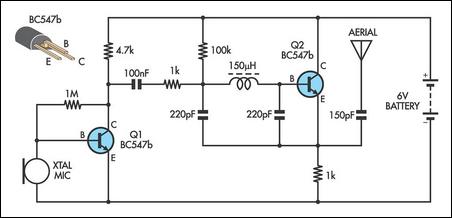
This AM transmitter design is notably simple to construct due to its use of a non-tapped inductor featuring a single winding. The inductor can be conveniently sourced as a standard RF choke, such as the Jaycar Cat LF-1536. To...
This is a range of IF signal circuits that may be of interest to radio hobbyists and professionals alike. Transistors T1 and T2 form an astable multivibrator oscillating in the audio frequency range of 1 to 2 kHz. An...
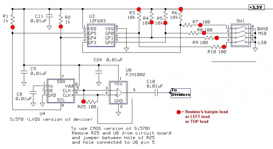
The current draw should be between 80 and 100 mA. The exact value is highly dependent on the Si570, its version (CMOS vs. LVDS), the frequency setting, and variations in the circuit components. The SW1 programming of U3 can...
The oscillator circuit involves two unity gain phase shift stages, A1 and A2, in tandem and a gain stage, A3, with back to back diodes and resistor network providing non-linear negative feedback. At a particular frequency (determined by RT...
With the rapid advancement of microelectronics and technology in information systems, digital technology represented by microcontrollers is evolving continuously. Microcontrollers are characterized by their small size, low power consumption, high expandability, and convenience in control functions. They are widely...
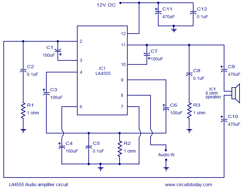
The LA4550 audio amplifier operates in a BTL (Bridge-Tied Load) configuration. This amplifier is capable of delivering 4W into an 8-ohm load when powered by a 12V power supply. The LA4550 is designed for audio amplification applications, particularly in situations...