
Local Oscillator Stage
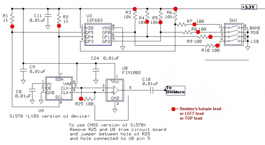
The described circuit operates within a current range of 80 to 100 mA, which is crucial for ensuring the proper functionality of the Si570 frequency generator. The Si570 can be configured in different versions, namely CMOS or LVDS, each affecting the current draw due to inherent differences in their electrical characteristics. The frequency setting also plays a significant role, as it can influence the load on the circuit and, consequently, the current consumption.
To assess the programming of the SW1 switch associated with the U3 component, voltage measurements should be taken at pins 1 through 7. It is expected that pins 1 to 3 maintain a stable DC voltage of approximately 3.27 VDC, indicating that the power supply and initial circuit conditions are functioning as intended. The voltages present at pins 4 through 7 will fluctuate based on the settings of the corresponding dip switches, which are critical for configuring the operational parameters of the circuit. Each dip switch setting alters the behavior of the circuit, allowing for flexibility in operation and performance.
In summary, careful monitoring of the current draw, along with the appropriate voltage levels at the designated pins, is essential for verifying the functionality and reliability of the circuit involving the Si570 frequency generator.The current draw should be somewhere between 80 and 100 mA. The exact value is very much dependent upon the Si570, the version (CMOS vs LVDS), the frequency setting, and component variations in the circuit. You can test the SW1 programming of U3 by checking the dc voltages at pins 1 thru 7. Pins 1 thru 3 should always be approximately 3. 27 Vdc. Vo ltages at pins 4 thru 7 will vary, depending upon their corresponding dip switch settings (pins 4 thru 7 correspond to dip switches 1 thru 4):. 🔗 External reference
Related Circuits
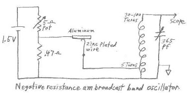
This circuit can be easily powered from a 1.5 volt battery. One characteristic of N type negative resistance devices is that they typically require a very low bias source resistance in order to keep the bias voltage stable within...
A 2N366 is configured as an audio feedback oscillator using an audio transformer. Adjust R1 for proper operation and the desired audio note. The circuit utilizes a 2N366 transistor, which is a general-purpose NPN transistor, serving as the primary active...
A square wave oscillator utilizing the 555 integrated circuit (IC) can be configured to produce symmetric oscillation with a 50% duty cycle. Additional circuit configurations employ diodes to separate the charging and discharging paths. The 555 timer IC is a...
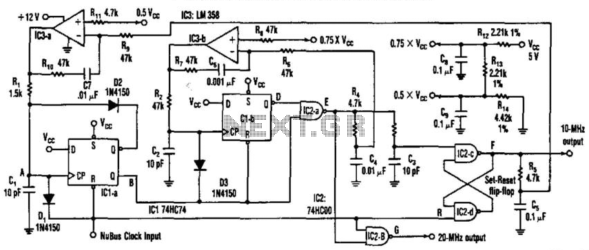
This circuit generates a 20-MHz clock signal that is phase locked to a 10-MHz clock found in the Apple MAC II. To create the 20-MHz output, the circuit generates a 25 ns negative-going pulse that is delayed by 50...
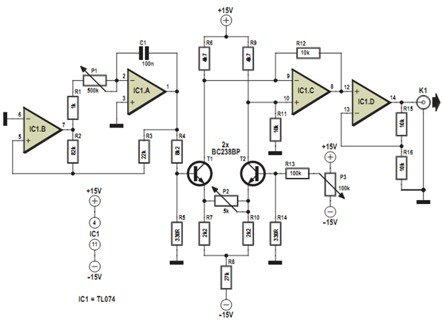
This design was developed to partially replace the well-known 8038 chip, which is no longer in production and therefore difficult to obtain. An existing design for driving a Linear Variable Differential Transformer (LVDT) sensor utilized the 8038 as a...
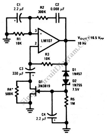
This is a Wien-bridge sine-wave oscillator circuit. This circuit utilizes negative-feedback stabilization to ensure that the gain does not exceed unity. The Wien-bridge oscillator is a type of electronic oscillator that generates sine waves. It consists of an amplifier and...