
Building a Sweep Generator for BK 4011
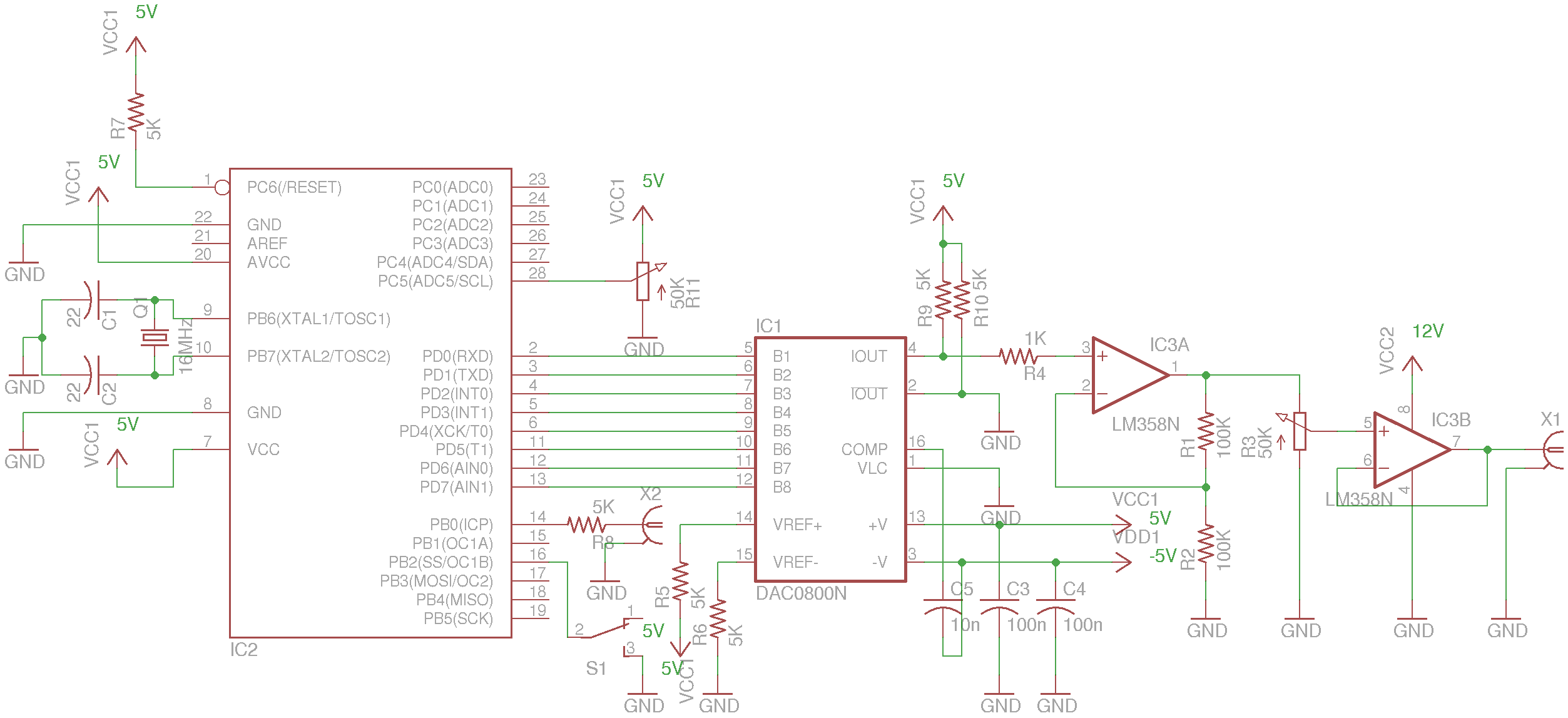
The schematic for the described sweep generator includes the following key components and connections. The Atmega328P microcontroller serves as the control unit, interfacing with the DAC0800 to generate the desired sweep waveform. The DAC0800 is connected to the microcontroller via an 8-bit data bus, utilizing PORTD for parallel data transfer, which allows for rapid updates to the DAC. The MAX889 charge pump provides the necessary negative voltage supply for the DAC0800, ensuring its operation within the required voltage specifications.
The output from the DAC0800 is first amplified by an LM358 Op-Amp configured in a non-inverting arrangement with a gain of 2, effectively doubling the voltage range. Following amplification, a potentiometer is incorporated to allow for fine-tuning of the output voltage, ensuring compatibility with the BK 4011's VCG input specifications. The final output is buffered through a second LM358 Op-Amp to maintain signal integrity and drive capability.
The microcontroller's firmware is structured to allow for real-time adjustments of the sweep frequency and mode, enabling the selection between linear and logarithmic sweep profiles. The TimerOne library is utilized to manage timing for the waveform generation, with interrupt-driven routines to facilitate the synchronization signal generation required by the function generator.
In summary, this circuit design provides a versatile and efficient solution for generating sweep waveforms compatible with the BK Precision 4011 function generator, leveraging the capabilities of the DAC0800 and the Atmega328P microcontroller to achieve the desired performance characteristics.A teardown of a BK Precision 4011 5MHz function generator a few weeks ago. Like most of basic function generators in old days, BK 4011 does not offer frequency sweep as an option. What it does include is a VCG (Voltage controlled Generator) input, which essentially is just a VCO and it can be used in conjunction with an external sweep genera
tor to generate frequency sweeps. In this post I will show you a simple sweep generator I built. It can be used to generate both the sweep waveform and synchronization signal needed for any function generator that has a VCG/VCO input. The sweep frequency can be adjusted from under a Hertz to several kHz. The sweep waveform can be switched between linear and logrithm modes and can be easily extended to accommodate other arbitrary waveforms.
At the core of this sweep generator lies an 8-bit parallel-input DAC DAC0800. This digital to analog converter is driven by an MCU (Atmega328P) which generates the sweep waveform. The reason that I used a parallel DAC in this situation is for its speed. While DAC0800 is a rather old chip, it can operate at a relatively fast speed which makes it suitable for waveform generation use.
It is also very inexpensive and easy to use. Modern DACs using serial protocols (e. g. SPI/I2C) on the other hand, can cost significantly more for the same operation speed. One draw back of using DAC0800 is that it requires dual supply rails for operation. While there are ways ( TI AN-1525 ) to use DAC0800 with a single supply, they add quite a bit of complexity to the circuit design. So to keep everything simple, I followed the dual supply route. To provide the negative voltage required by DAC0800 I used Maxim`s MAX889 inverting charge pump. Because BK 4011 ²s VCG input range is 0-10V, the output from DAC0800 is amplified by a x2 non-inverting Op-Amp.
And the output from the x2 amplifier is then attenuated by a potentiometer to obtain the full VCG voltage range. Finally, the attenuated sweep waveform is buffered through another Op-Amp. The dual Op-Amp chip used here is LM358, since it is not a rail-to-rail Op-Amp, the actual adjustable output voltage range is slightly less and will not reach 0V.
For this simple sweep generator, this limitation shouldn`t matter much. The full code listing is shown below. The code was compiled using Arduino 1. 0. 1, but it should be compatible with pretty much all Arduino IDE versions. The TimerOne library can be downloaded from here. #include
initialize(sweepInterval); } } void timer1Callback() { if (sweepMode = LOG_SWEEP) { PORTD= EEPROM. read(b); b+; if (b=255) { b=0; //generate a synchronization signal PORTB |= 1; delayMicroseconds(10); PORTB &= 0xFE; } } else if (sweepMode = LINEAR_SWEEP) { b-; PORTD=255-b; if (b=0) { b=255; //generate a synchronization signal PORTB |= 1; delayMicroseconds(10); PORTB &= 0xFE; } } } Note that PORTD (digital pin 0 through digital pin 7) is used to drive the 8 bit DAC data line. This is the fastest way to manipulate the DAC as the bits in the same port can be altered in a single operation.
Since Pin 0 and Pin 1 are for serial co 🔗 External reference
Related Circuits
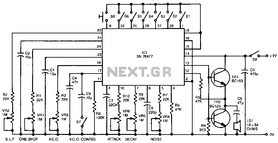
Six preset controls and seven selector switches enable a vast range of different sounds to be produced and altered at will. Such sounds as steam trains chuffing, helicopters flying, bird chirping, and machine guns firing are possible, as well...
A high-quality tone burst generator can be constructed using a 556 Dual Timer. The first half of the timer can be configured as a one-shot, while the second half can function as an oscillator. The 556 Dual Timer is an...
This is a 555 tone generator circuit based on the NE555 timer IC. The NE555 is a well-known integrated circuit utilized in various applications and performs a multitude of functions. In this circuit, the IC operates as an astable...
An electromagnetic generator without moving parts consists of a permanent magnet and a magnetic core that includes first and second magnetic paths. A first input coil and a first output coil are positioned around sections of the first magnetic...
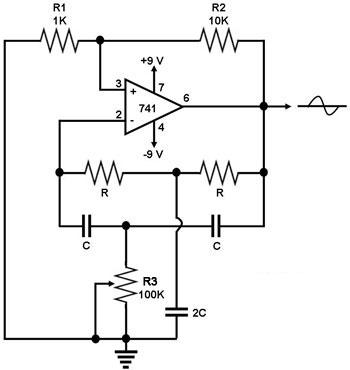
This circuit generates a sine wave using a single operational amplifier (741). The feedback loop of the op-amp includes a twin-T filter connected between its output and inverting input. Positive feedback for oscillation is provided by resistor R2. The...
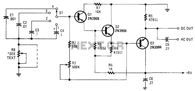
Seven narrow pulses ranging from 2 Hz to 50 kHz are generated by this circuit. Capacitors C1 through C4 provide frequency ranges in decode steps. Resistors R1 and R2 regulate the charging time of capacitors C1 through C4. R2...
Warning: include(partials/cookie-banner.php): Failed to open stream: Permission denied in /var/www/html/nextgr/view-circuit.php on line 713
Warning: include(): Failed opening 'partials/cookie-banner.php' for inclusion (include_path='.:/usr/share/php') in /var/www/html/nextgr/view-circuit.php on line 713