
sine wave generator circuit
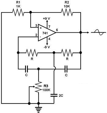
The sine wave generator circuit utilizing a single operational amplifier (741) is an effective design for generating sinusoidal waveforms. The operational amplifier is configured in a negative feedback arrangement with a twin-T notch filter, which is critical for achieving the desired oscillation. The twin-T filter is characterized by its unique configuration of resistors and capacitors, allowing it to create a notch in the frequency response at the specified frequency fn = 1/(2πRC).
In this configuration, one T-network consists of a resistor and two capacitors, while the second T-network is composed of two resistors and one capacitor. This arrangement ensures that at the notch frequency, the phase shift around the feedback loop is precisely zero degrees, which is a necessary condition for sustained oscillation. The resistor R2 is essential in providing the necessary positive feedback to enable the op-amp to oscillate.
The operational amplifier's output, which is a sine wave, can be adjusted for amplitude and frequency by modifying the values of the resistors and capacitors in the twin-T filter. This flexibility makes the circuit suitable for various applications, including signal generation, waveform shaping, and testing of audio equipment. The design is straightforward and cost-effective, leveraging the characteristics of passive components to achieve stable oscillations.
Overall, this sine wave generator circuit is a practical example of using operational amplifiers in waveform generation, demonstrating the fundamental principles of feedback and frequency response in electronic circuit design.This is a circuit for generating a sine wave from a single operational amplifier. The feedback loop of the op amp in this circuit (741) consists of a twin-T filter connected between its output and its inverting input. Positive feedback for oscillation is provided by R2. The twin-T filter (see Figure 2) is a passive notch filter composed of two T-n etworks, with maximum attenuation occurring at fn = 1/(2pRC). One of these T networks has one resistor and two capacitors, while the other has two resistors and one capacitor. At the notch frequency fn of the twin-T filter, the total phase shift around the loop gain of this op amp circuit is zero, which satisfies the requirement for oscillation.
This is why the circuit generates a sine wave with a frequency equal to fn = 1/(2pRC). 🔗 External reference
Related Circuits
This circuit will activate a relay when light falls to a preset level. Light level can be adjusted with VR1 and the relay contacts may be used to operate an external light or buzzer. More: The light sensor used...
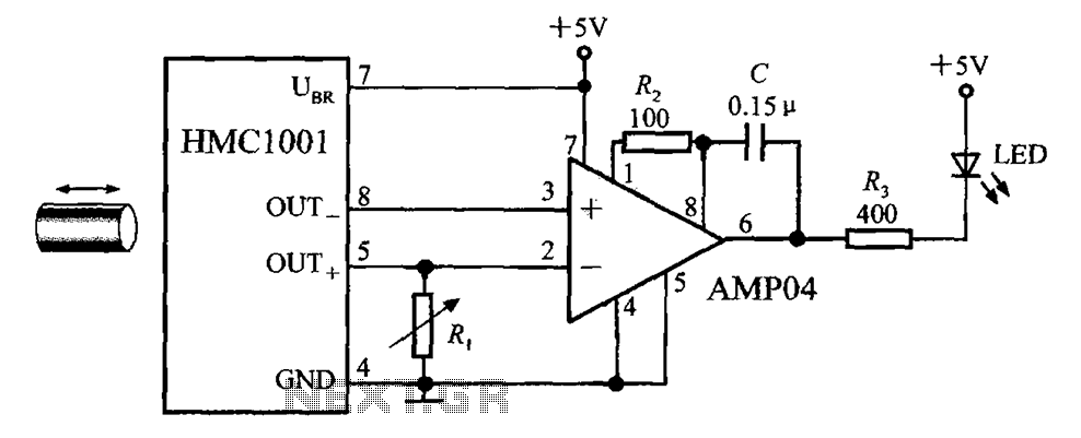
The circuit depicted in the figure includes the HMC1001 magnetic sensor, an operational amplifier (AMP04), and a light-emitting diode (LED), forming a proximity switch circuit. In this application, the operational amplifier functions as a comparator. When a magnet, approximately...
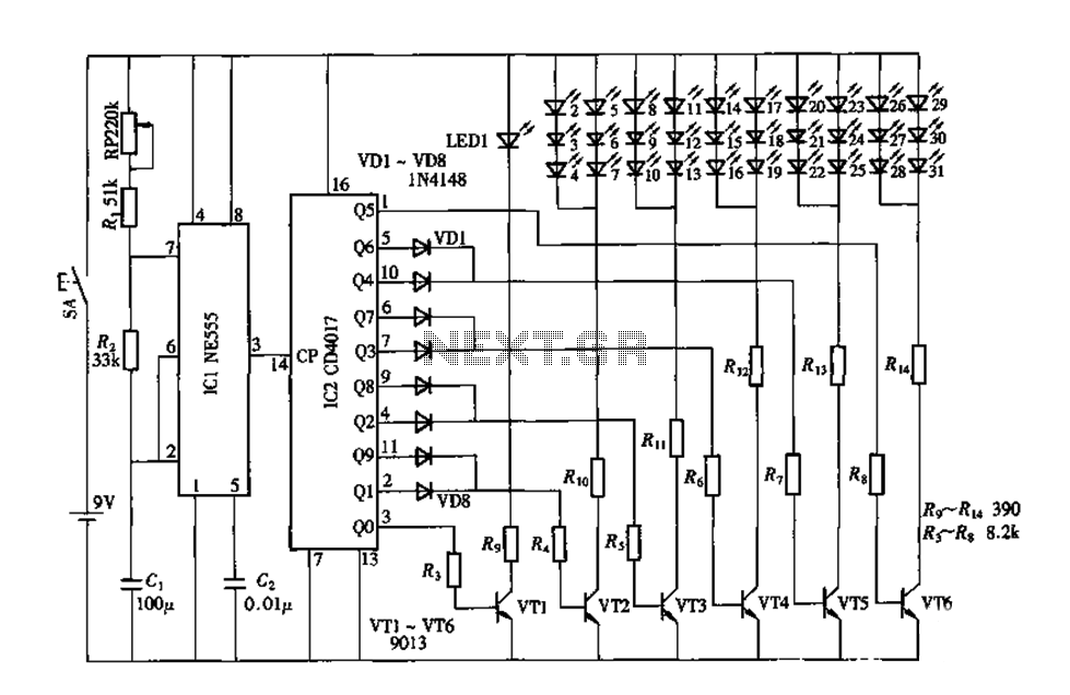
An electronic decorative peacock consists of 10 light-emitting diodes (LEDs), each of which contains multiple LEDs arranged in the tail of the peacock model. The light emission drive circuit operates the fan-shaped LEDs in a cyclic manner, emitting light...
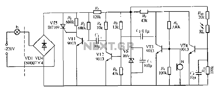
This circuit describes a sound and light control delay system for a walkway stairs light switch. It involves various components including 220V AC electric bulbs, diodes (VD1-VD4), and resistors. The circuit utilizes a rectifier regulator to stabilize the voltage...
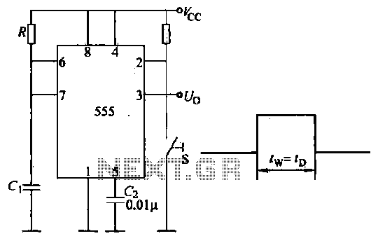
Introduction to the circuit schematic depicted in Figure 3-3. In this configuration, the 555 timer is utilized in a monostable mode, typically activated by a normally open push button switch. The circuit operates in an S-shaped state, where the...
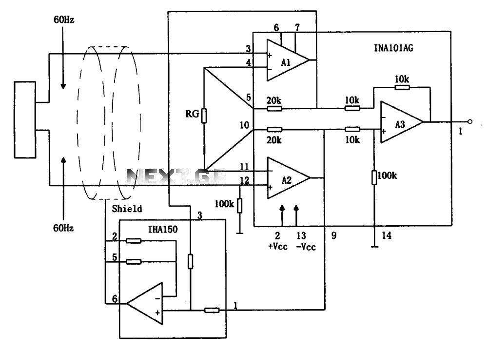
The circuit diagram illustrates a hum elimination instrument amplifier circuit. The amplifier stages A1 and A2 utilize the integrated operational amplifier INA101, followed by stage A3 which employs the INA105. A feedback circuit is incorporated to reduce the power...