
Burglar-alarm
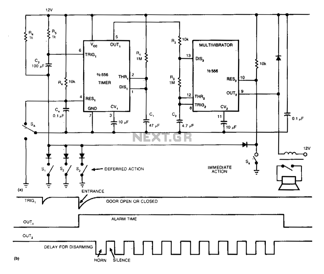
The single-chip burglar alarm circuit utilizes a dual 556 timer, drawing 10 mA of standby current, and produces a pulsing alarm signal that conserves battery energy. Once activated, the alarm remains operational, independent of the subsequent state of any sensors. The sensors can operate in both deferred and immediate-action modes. This circuit can be connected to the car's internal lighting system using a single wire and a relay. To arm the circuit, the user opens the car door and closes switch SA. This action discharges capacitor C4 and keeps one half of the 556 timer in a reset state to prevent false triggering while arming the circuit. When the car door is closed, the circuit enters standby mode.
If the door is reopened, the sensors send a negative-going pulse to trigger 1. Output 1 then increases, activating the alarm for a duration of 1.1R1C1 seconds. The high state of Output 1 triggers the multivibrator, which is the other half of the 556 timer, initiating a cycling process after a delay equal to 1.1(R2 + R3)C2 seconds. As long as the timer's output remains high, the multivibrator will continue to cycle, turning the horn on and off at 3.3-second intervals. During the time between the increase in the timer's output and the decrease in the multivibrator's output, the circuit can be disarmed using switch SA. To avoid false triggering due to switch contacts at S1, S2, and S3 that may bounce when the door is closed, it is advisable to make the R6C3 time constant as large as possible. Furthermore, capacitors C1 and C2 should be tantalum types with a leakage current of less than 1 µA at room temperature.
The circuit design employs a dual 556 timer IC, which consists of two 555 timer circuits in one package. The first timer is configured in monostable mode to create a delay for the alarm activation, while the second timer operates in astable mode to generate the pulsing alarm signal. The use of tantalum capacitors is critical due to their low leakage characteristics, ensuring that the timing intervals remain accurate and that the circuit remains energy-efficient.
The integration of the relay allows for seamless connection to the car's existing lighting system, enabling the alarm to be activated without complex wiring. The choice of resistors R1, R2, R3, and R6, along with the capacitors C1, C2, C3, and C4, determines the timing characteristics of the circuit, allowing for customization based on the desired alarm duration and sensitivity to door operation.
In terms of safety and reliability, the circuit is designed to minimize the risk of false alarms through the implementation of debouncing techniques, ensuring that the alarm is only triggered by intentional actions. The overall design is compact, efficient, and suitable for automotive applications, providing an effective solution for vehicle security.The single-chip, burglar -alarm circuit shown uses a dual 556 timer, draws 10 mA of standby current, and generates a pulsing alarm signal that conserves battery energy. Once activated, the alarm wilLremain on, independent of the subsequent state of any of the sensors. The sensors support both deferred and immediate-action modes. You can attach this circuit to your car"s internal lighting circuitry using a single wire and a relay.
To arm this circuit, you open your car door and close switch SA. The switch discharges capacitor C4 and holds the timer (one half of the 556 !C) in a reset state to prevent false triggering while you"re arming the circuit. When you close your car door, the circuit enters a standby mode. If the door is then reopened, the sensors apply a negative-going pulse to trigger 1. Output 1 then increases, enabling the alarm for 1.1R1C1 seconds. Output 1 "s high state triggers the multivibrator, the other half of the 556, which begins to cycle after a delay equal to 1.1 (R2 + R3) C2 seconds. As long as the timer"s output stays high, the multivibrator will continue to cycle, turning the horn off and on at 3.3-second intervals.
During the interval between time that the timer"s output increases and the time that the multivibrator"s output decreases, you can disarm this circuit using switch SA. To prevent false triggering caused by switch contacts, at S1, S2, and S3, that may bounce when closing the door, make the R6C3 time constant as large as possible.
In addition, capacitors C1 and C2 should be tantalum types and should exhibit leakage of less than 1 11A at room temperature. 🔗 External reference
Related Circuits
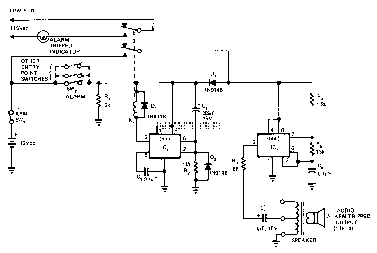
This circuit cannot be shut off for 10 to 60 seconds, even if the trip condition is immediately removed. It draws no standby power from the battery and is self-resetting. The described circuit operates under a delay mechanism that...
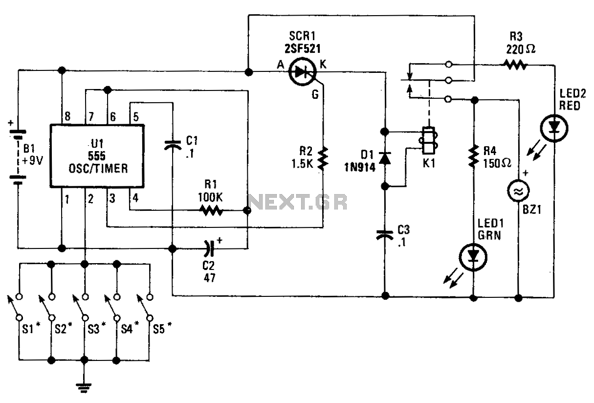
The core component of the circuit is a 555 timer/oscillator, designated as U1, which is configured for monostable operation. The output from U1 at pin 3 is connected to the gate of SCR1. As long as switches S1 to...