
cable tv signal booster amplifier
The cable TV signal booster amplifier circuit is structured to improve the quality and reliability of cable television signals, particularly in areas where signal strength is weak or prone to interference. The use of 75 Ohm coaxial cables ensures optimal impedance matching, which is crucial for minimizing signal loss and maximizing performance.
Transistor Q1, as the primary amplification component, is selected for its high-frequency response and low noise characteristics, which are essential for maintaining signal integrity at the frequencies of interest. The configuration of Q1 is typically a common-emitter amplifier, providing significant voltage gain. Transistor Q2, configured as an emitter follower, serves to buffer the output of Q1, presenting a low output impedance to the subsequent stages or load. This configuration helps isolate the amplifier from the load, ensuring that the gain remains stable regardless of variations in load impedance.
The circuit's gain of 20 dB or more indicates that it can effectively increase the amplitude of weak signals, making it suitable for applications where long cable runs or multiple splitters may attenuate the signal strength. The low current consumption of 20 mA highlights the efficiency of the design, allowing it to operate with minimal power requirements, which is particularly advantageous in portable or battery-operated applications.
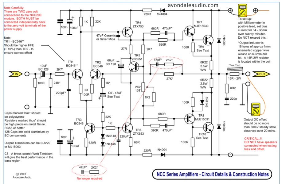
Overall, this cable TV signal booster amplifier circuit is an essential component for enhancing cable television reception, ensuring that users receive a clear and consistent signal for optimal viewing experiences. Proper implementation and housing within a metal case also contribute to reducing electromagnetic interference, further improving performance.This is a schematic of a cable TV signal booster amplifier circuit which can be used to amplify or boost the signal of cable TV system. Use 75 Ohm coaxial cables at the input and output of the circuit and fit the circuit in a metal case.
The bandwidth of the circuit is up to 150MHz. Transistor Q1 is used to amplify the signal and Q2 is working as an emitter follower. The circuit will provide gain of 20dB or more. The current consumption of the circuit is only 20mA. 🔗 External reference
Related Circuits
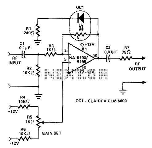
This circuit operates as a wideband adjustable automatic gain control (AGC) amplifier. It has an effective bandwidth of approximately 10 MHz and can handle RF input signal frequencies ranging from 3.2 to 10 MHz at levels between 40 mV...
The following circuit diagram illustrates a simplified application circuit for the TDA8932B/33(B) device when it is powered by an asymmetrical supply (single supply). The TDA8932B/33(B) is a class-D audio amplifier integrated circuit designed for efficient audio amplification in various applications....
Can be directly connected to CD players, tuners and tape recorders. Simply add a 10K Log potentiometer (dual gang for stereo) and a switch to cope with the various sources you need. Q6 & Q7 must have a small...
This circuit illustrates a Car Radio Audio Amplifier using the TDA2003 integrated circuit. The datasheet for the TDA2003 includes electrical characteristics and schematic wiring details. The TDA2003 is a high-performance audio amplifier designed for automotive applications. It is capable of...

This design outlines a simple wideband output amplifier suitable for use as a 50-ohm transmission line driver. The circuit is constructed using the CA3140 operational amplifier. When utilized alongside the function generator and sine wave shaper circuits, it delivers...
This is a simple circuit that features high-performance power amplifiers. The power amplifier is available as a PCB, along with a complete list of components. The described circuit utilizes high-performance power amplifiers, which are essential for applications requiring significant signal...