
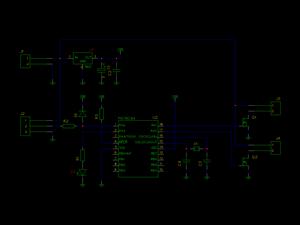
Mosfet amplifier schematic 25 Watt


R1,R4 = 47K 1/4W Resistors
R2 = 4K7 1/4W Resistors R3 = 1K5 1/4W Resistors R5 = 390R 1/4W Resistors R6 = 470R 1/4W Resistors R7 = 33K 1/4W Resistors R8 = 150K 1/4W Resistors R9 = 15K 1/4W Resistors R10 = 27R 1/4W Resistors R11 = 500R 1/2W Trimmer Cermet
R12,R13,R16 = 10R 1/4W Resistors R14,R15 = 220R 1/4W Resistors R17 = 8R2 2W Resistor R18 = R22 4W Resistor (wirewound)
C1 = 470nF 63V Polyester Capacitor C2 = 330pF 63V Polystyrene Capacitor C3,C5 = 470µF 63V Electrolytic Capacitors C4,C6,C8,C11 = 100nF 63V Polyester Capacitors C7 = 100µF 25V Electrolytic Capacitor C9 = 10pF 63V Polystyrene Capacitor C10 = 1µF 63V Polyester Capacitor
Q1-Q5 = BC560C 45V100mA Low noise High gain PNP Transistors Q6 = BD140 80V 1.5A PNP Transistor Q7 = BD139 80V 1.5A NPN Transistor Q8 = IRF532 100V 12A N-Channel Hexfet Transistor Q9 = IRF9532 100V 10A P-Channel Hexfet Transistor
R1 = 3K3 1/2W Resistor
C1 = 10nF 1000V Polyester Capacitor C2,C3 = 4700µF 50V Electrolytic Capacitors C4,C5 = 100nF 63V Polyester Capacitors
D1 200V 8A Diode bridge D2 5mm. Red LED F1,F2 3.15A Fuses with sockets
T1 220V Primary, 25 + 25V Secondary 120VA Mains transformer
PL1 Male Mains plug
SW1 SPST Mains switch
The described circuit is a versatile audio amplifier that accommodates various audio sources such as CD players, tuners, and tape recorders. The integration of a 10K logarithmic potentiometer in dual-gang configuration allows for stereo volume control, facilitating user-friendly operation across different audio inputs.
The transistors Q6 and Q7, which are critical components in the amplification stage, require proper thermal management and should be equipped with small U-shaped heatsinks. The power transistors Q8 and Q9 necessitate mounting on substantial heatsinks to dissipate heat effectively, ensuring reliable performance and longevity.
The quiescent current is adjustable via the trimmer resistor R11, which should be calibrated to 100mA. This adjustment is best performed with an ammeter in series with the drain of Q8, ensuring optimal operation without an input signal.
Grounding is a key aspect of the design, as improper grounding can lead to hum and ground loops. It is essential to connect the ground terminals of resistors R1, R4, R9, and capacitors C3 to C8 at a single point. Additionally, capacitor C11 should be connected to the output ground, while the input and output grounds should be separately linked to the power supply ground.
The amplifier exhibits an output power exceeding 25 Watts RMS at 8 Ohms, with a sensitivity of 200mV input for a 25W output. The frequency response ranges from 30Hz to 20kHz with a tolerance of -1dB, and the total harmonic distortion (THD) is minimal across various power levels, indicating high fidelity in audio reproduction.
The circuit also includes protective components such as diodes and fuses, ensuring safe operation under various conditions. The mains transformer T1 is rated for 220V primary and provides a secondary output of 25 + 25V at 120VA, suitable for powering the amplifier.
Overall, this amplifier circuit is designed for high performance and reliability, with careful consideration given to component selection, thermal management, and grounding practices.Can be directly connected to CD players, tuners and tape recorders. Simply add a 10K Log potentiometer (dual gang for stereo) and a switch to cope with the various sources you need. Q6 & Q7 must have a small U-shaped heatsink. Q8 & Q9 must be mounted on heatsink. Adjust R11 to set quiescent current at 100mA (best measured with an Avo-meter in series with Q8 Drain) with no input signal.
A correct grounding is very important to eliminate hum and ground loops. Connect in the same point the ground sides of R1, R4, R9, C3 to C8. Connect C11 at output ground. Then connect separately the input and output grounds at power supply ground. Technical data: Output power: well in excess of 25Watt RMS @ 8 Ohm (1KHz sinewave). Sensitivity: 200mV input for 25W output. Frequency response: 30Hz to 20KHz -1dB. Total harmonic distortion @ 1KHz: 0.1W 0.014% 1W 0.006% 10W 0.006% 20W 0.007% 25W 0.01%. Total harmonic distortion @10KHz: 0.1W 0.024% 1W 0.016% 10W 0.02% 20W 0.045% 25W 0.07%. R1,R4 = 47K 1/4W Resistors R2 = 4K7 1/4W Resistors R3 = 1K5 1/4W Resistors R5 = 390R 1/4W Resistors R6 = 470R 1/4W Resistors R7 = 33K 1/4W Resistors R8 = 150K 1/4W Resistors R9 = 15K 1/4W Resistors R10 = 27R 1/4W Resistors R11 = 500R 1/2W Trimmer Cermet R12,R13,R16 = 10R 1/4W Resistors R14,R15 = 220R 1/4W Resistors R17 = 8R2 2W Resistor R18 = R22 4W Resistor (wirewound) C1 = 470nF 63V Polyester Capacitor C2 = 330pF 63V Polystyrene Capacitor C3,C5 = 470µF 63V Electrolytic Capacitors C4,C6,C8,C11 = 100nF 63V Polyester Capacitors C7 = 100µF 25V Electrolytic Capacitor C9 = 10pF 63V Polystyrene Capacitor C10 = 1µF 63V Polyester Capacitor Q1-Q5 = BC560C 45V100mA Low noise High gain PNP Transistors Q6 = BD140 80V 1.5A PNP Transistor Q7 = BD139 80V 1.5A NPN Transistor Q8 = IRF532 100V 12A N-Channel Hexfet Transistor Q9 = IRF9532 100V 10A P-Channel Hexfet Transistor R1 = 3K3 1/2W Resistor C1 = 10nF 1000V Polyester Capacitor C2,C3 = 4700µF 50V Electrolytic Capacitors C4,C5 = 100nF 63V Polyester Capacitors D1 200V 8A Diode bridge D2 5mm. Red LED F1,F2 3.15A Fuses with sockets T1 220V Primary, 25 + 25V Secondary 120VA Mains transformer PL1 Male Mains plug SW1 SPST Mains switch
🔗 External reference
Related Circuits
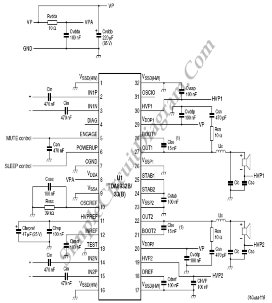
The following circuit diagram illustrates a simplified application circuit for the TDA8932B/33(B) device when it is powered by an asymmetrical supply (single supply). The TDA8932B/33(B) is a class-D audio amplifier integrated circuit designed for efficient audio amplification in various applications....
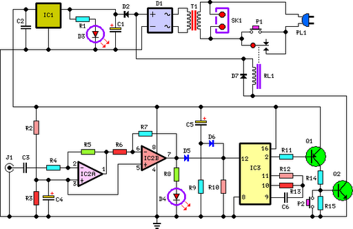
This circuit deactivates an amplifier or any connected device when a low-level audio signal at its input is absent for at least 15 minutes. Pressing P1 turns the device on, supplying power to any appliance connected to SK1. The...
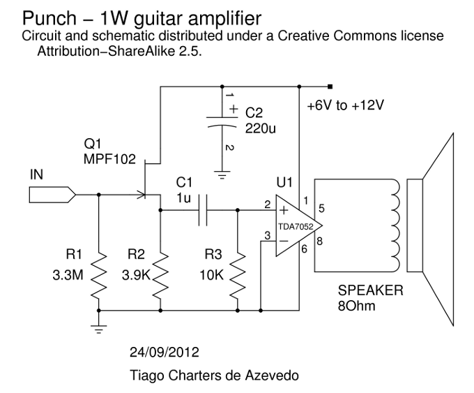
An alternative to the well-known ROG Ruby amplifier, this design shares a similar topology, featuring a buffer and a chip amplifier. It employs a JFET buffer utilizing the MPF102, along with the 1W TDA7052 chip. The amplifier delivers a...
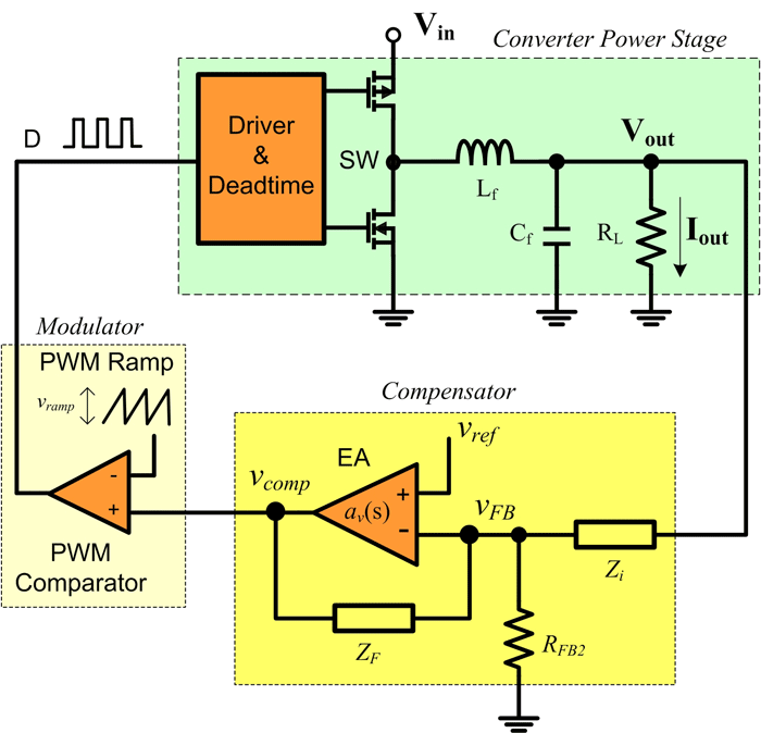
As power supply switching frequencies increase, higher loop crossover frequencies are necessary to keep pace with the escalating load transient slew rate demands and to reduce the number and size of filter components. For voltage-mode-controlled supplies, the voltage loop...
To quickly determine if a remote control transmitter is functioning properly, a remote control detector can be utilized. If the remote control transmitter is operational, the detector will emit an audible alarm signal. This detector is capable of assessing...
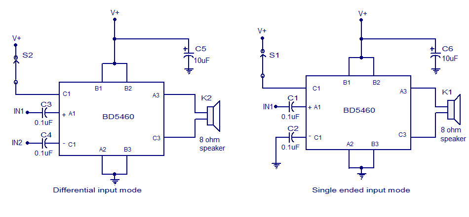
The BD5460 is a low power Class D amplifier that can be utilized in low power applications such as handheld audio devices. The BD5460 does not require an LC filter at the speaker output and can be powered by...