
Camera external shutter circuit 555 timer
The circuit design incorporates a 555 timer IC configured in astable mode, allowing it to produce a square wave output that can be used to trigger the camera shutter at specified intervals. The frequency of this output can be adjusted by changing the resistor and capacitor values connected to the timer. The use of an acceleration switch introduces a level of automation, ensuring that the camera begins to take pictures only after detecting the specific motion associated with liftoff.
The integration of the ASA3T acceleration switch is crucial, as it not only activates the timer but also prevents false triggers from minor disturbances. The design should ensure that the power supply is stable and that the connections are secure to avoid any interruptions during operation. The use of a custom PC board allows for a compact and organized layout, minimizing the risk of short circuits and enhancing reliability.
Additionally, using a socket for the 555 timer is advisable, as it facilitates easy replacement of the IC without the need for desoldering, which can be particularly important in field applications where the circuit may experience various environmental conditions. The arming plug serves as a safety feature, allowing the operator to disable the timer before launch, thus protecting against unintended activation.
In summary, this circuit effectively combines a 555 timer and an acceleration switch to automate the triggering of a camera shutter at regular intervals post-launch, with safety and reliability being key considerations in its design and implementation.Having wired the camera with external shutter leads I now needed a way to trip them. They needed to be tripped (i. e. connected together via a relay) at a regular interval, perhaps 2 seconds, starting at launch. I had read that a 555 timer chip configured as a multivibrator can work. I purchased Engineer`sas a timer. Mini-Notebook, 555 Timer Circuits and found the basis for the circuit I would need. For launch detection I chose an acceleration switch from Adept Rocketry. The acceleration switch and timer were both powered by a single 9V battery. I built and tested the circuit using a breadboard and then implemented it using a Radio Shack PC board kit (Cat. No. 276-1576). This allowed me to etch my own PC board. If you decide the make your own board for the circuit you will need a 3/64" drill bit. These can be a little tough to find but larger drill bits will make holes that are too large and make soldering very difficult.
I discovered this the hard way. I also recommed a socket for the 555 IC as heat from soldering can damage ICs. The ASA3T acceleration switch is smart enough to differentiate a bump or jar from liftoff but I chose to add an arming plug (1/8" Phono plug) just to be safe. Once prepped and loaded if the timer starts accidentally there is no way to stop it before it wastes a whole roll of film.
While not strictly necessary it is recomended. The Yellow and Orange wires terminate in a Dean`s connector and connect to the Camera`s shutter wires. The Red and Black pair of wires connect to the output of an Adept ASA3T Acceleration Switch. This device (shown below oriented horizontally) senses liftoff and powers the timer circuit using via the same 9V bettery powering the ASA3T.
There is a POT on the ASA3T that allows it to be configured to power up the timer anywhere from 1/2 to 15 seconds after liftoff. When used in AYUCR the time delay is set to the minimum. 🔗 External reference
Related Circuits
Setting circles on an astronomical telescope are used as an aid to point the telescope at a specific object in the sky based on the object's celestial coordinates. However, setting circles can be challenging to use effectively and are...
This Intercom is powered by two 9-volt batteries and uses only current when the Intercom is used. Both units are connected via a two-wire little cable or simply two wires (dotted lines). The loudspeakers act both as loudspeakers and...

This circuit represents a remote control unit that utilizes radio frequency signals to operate various electrical appliances. The remote control unit features four channels, which can be expanded to twelve. This circuit stands out from similar designs due to...
The circuit integrates several functions, including a smooth startup for the AC power line, with a one-second delay before connecting to the power supply transformers of the amplifier through relay RL1 and resistor Rx. This delay is designed to...
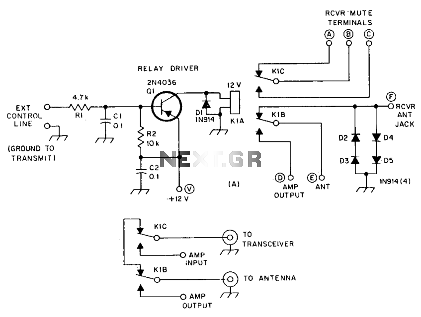
R1 and R2 are carbon composition resistors labeled as Va or Vi. K1 is a 12 V DPDT DIP relay. Illustration A demonstrates the connection of the relay contacts for use with a separate transmitter-receiver combination. The circuit is...
The ignition coil driver circuit described is a highly regarded design, reportedly created by Jochen Kronjaeger. It is intended to operate from a 230V source, although a modified version can function effectively at 120V. The circuit requires two ignition...
Warning: include(partials/cookie-banner.php): Failed to open stream: Permission denied in /var/www/html/nextgr/view-circuit.php on line 713
Warning: include(): Failed opening 'partials/cookie-banner.php' for inclusion (include_path='.:/usr/share/php') in /var/www/html/nextgr/view-circuit.php on line 713