
Tr circuit

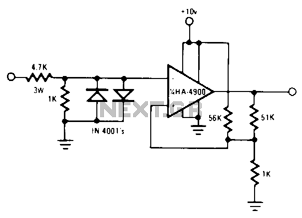
The circuit utilizes R1 and R2, which serve as load resistors, critical for setting the appropriate voltage levels in the circuit. These resistors ensure that the relay operates within its specified parameters, allowing for reliable switching. The 12 V DPDT (Double Pole Double Throw) relay, K1, provides the necessary control over the signal path, enabling seamless transitions between different operational modes of the transceiver.
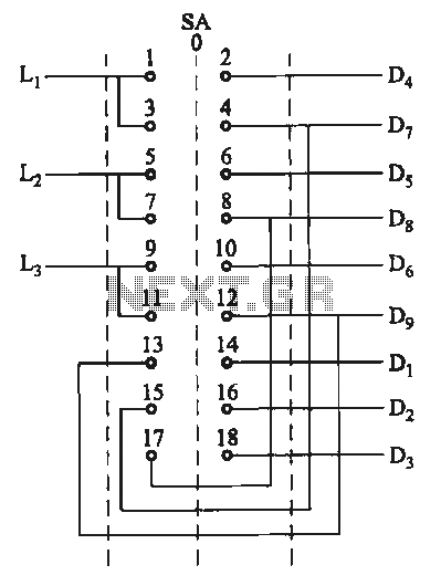
Illustration A outlines the relay contact configuration essential for integrating the circuit with an external transmitter-receiver setup. This configuration is vital for applications requiring precise control over signal routing, enhancing communication efficiency. The relay contacts can be wired to switch between different signal paths, ensuring that the amplifier can operate effectively with the transceiver.
C1 and C2, being disc ceramic capacitors, are employed for decoupling and filtering purposes. Their role is to stabilize the voltage supply to the relay and prevent high-frequency noise from affecting the performance of the amplifier and transceiver. The choice of ceramic capacitors offers low equivalent series resistance (ESR) and high-frequency response, making them suitable for this application.
Overall, this circuit design integrates resistors, a relay, and capacitors to create a robust amplifier system capable of interfacing with a transceiver, ensuring reliable performance in communication applications.R1 and R2 are Va or Vi W carbon composition resistors. K1 is a 12 V DPDT DIP relay. Illustration A shows how to connect the relay contacts for use with a separate transmitter-receiver combination. The circuit at is for amplifier use with a transceiver. Cl and C2 are disc ceramic.
Related Circuits
The heating element is connected in series with two back-to-back 16 amp silicon-controlled rectifiers (SCRs), which are controlled by a small pulse transformer. This pulse transformer features three identical windings; two of these windings provide trigger pulses to the...
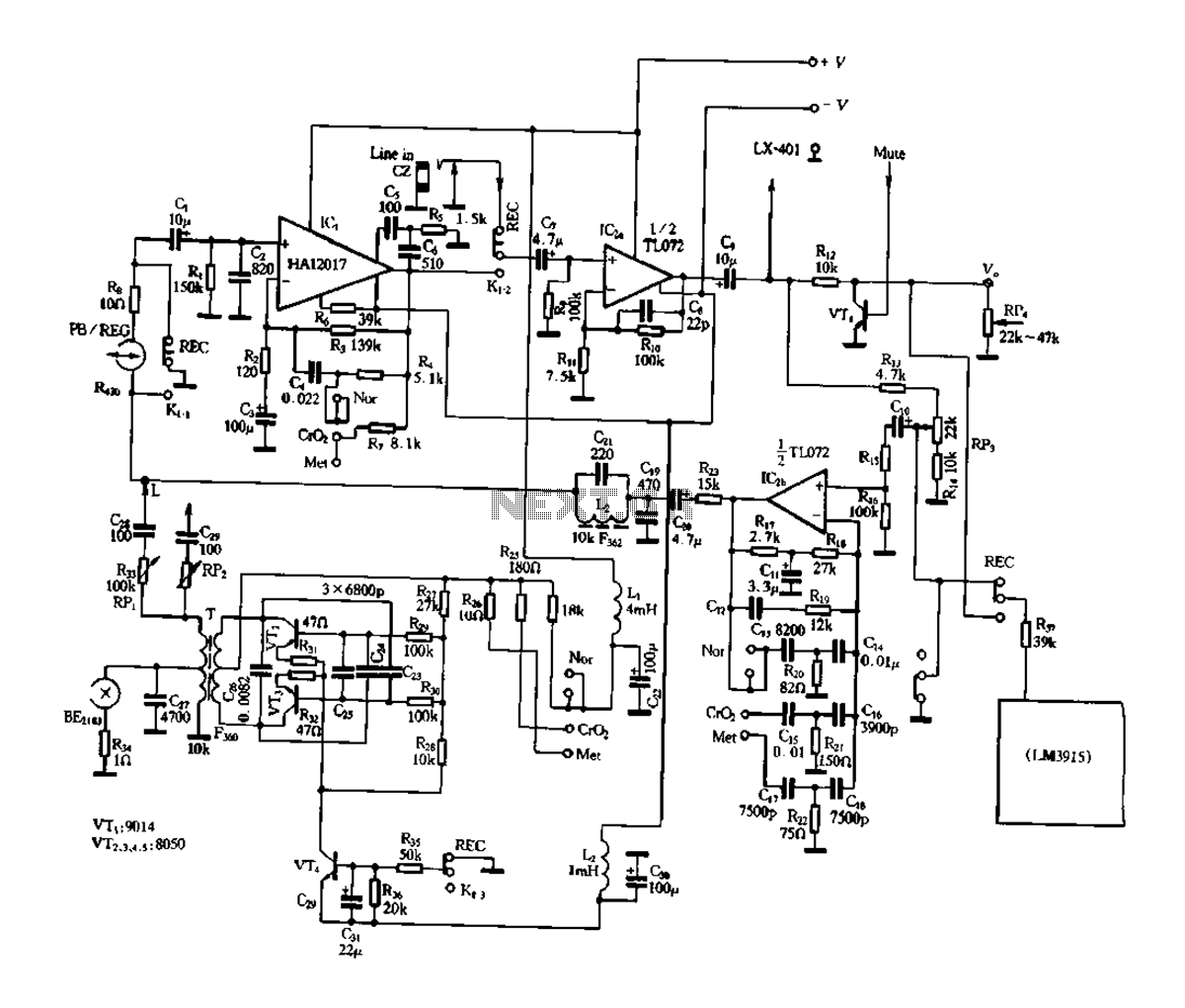
Figure 3-17 illustrates a pre-equalizer amplifier with sound recording capabilities, featuring the following characteristics: (1) The circuit does not utilize a conventional mechanical switch circuit; instead, it employs fully enclosed electromagnetic relays. This design allows for a core and...
Utilize a pair of Maxim's 5V-powered MAX231 RS-232C transmitters as drivers to achieve a dual-color LED. These transmitters necessitate only a single-ended, 5-V input to internally generate ±10 V. Their outputs are designed to be short-circuit-proof and can provide...
The motor switch control circuit depicted in the figure provides two speed settings for counter-steering, allowing for operation at two speeds in opposite directions. The motor switch control circuit is designed to facilitate the operation of a motor at two...
A common issue with small flashlights is the limited lifespan of both the batteries and the bulb. For example, a typical incandescent flashlight consumes approximately 2 Watts, while the LED flashlight shown in Fig. 1 consumes only 24 mW....
This is an aerial current power supply with a continuously adjustable stabilized output ranging from 0 to 30VDC. The circuit also incorporates an electronic current limiter that effectively controls the output current from a few milliamperes (2 mA) to...