
capacitor Choosing components for a triacs snubber
The interfacing of the BT139-600 TRIAC with the MOC3051-M Opto-triac is a common approach in controlling AC loads, particularly for applications like motor control. The BT139-600 is a sensitive gate TRIAC capable of handling high voltage and current, making it suitable for switching applications. The MOC3051-M serves as an opto-isolator, providing electrical isolation between the control circuit and the high-voltage load.
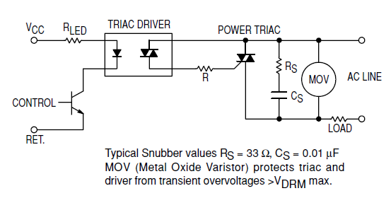
To construct the snubber circuit, the resistor (Rs), capacitor (Cs), and MOV must be selected based on the load characteristics and expected transient conditions. The resistor should be rated for power dissipation that can handle the energy during transient events. Typically, a resistor with a power rating of at least 1W is recommended, though this may vary depending on the specific application and expected transients.
The capacitor (Cs) should be a film capacitor rated for AC applications, typically with a voltage rating of at least 1.5 times the supply voltage, which in this case would be around 350V or higher to ensure reliability. A capacitance value in the range of 0.1µF to 0.47µF is commonly used, but this should be determined based on the specific energy dissipation requirements of the motor being controlled.
The MOV is crucial for protecting the circuit from voltage spikes. It should be rated for a clamping voltage that is higher than the peak voltage of the AC supply but low enough to protect sensitive components in the circuit. Selecting an MOV with a voltage rating of around 300V to 400V would be appropriate for a 230V AC application.
The snubber circuit's primary function is to absorb the transient energy generated when the TRIAC switches off, preventing voltage spikes that could damage the TRIAC or other components in the circuit. It acts as an energy sink, allowing the transient energy to dissipate safely and ensuring stable operation of the TRIAC and connected load.
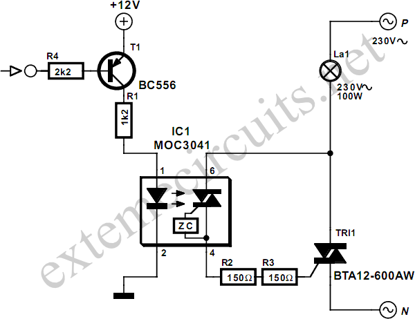
A circuit diagram for this configuration would include the BT139-600 TRIAC connected in series with the load (motor), with the MOC3051-M providing the control signal. The snubber circuit, consisting of Rs, Cs, and MOV, would be connected in parallel to the TRIAC to effectively manage transients and protect the circuit.
In conclusion, careful selection of the resistor, capacitor, and MOV, along with proper circuit design, is essential for the effective interfacing of the BT139-600 TRIAC with the MOC3051-M Opto-triac in controlling a 230V AC motor while ensuring reliability and safety.Interfacing the BT139-600 TRIAC with this MOC3051-M Opto-triac. Build a snubber circuit for the TRIAC as shown in the MOC3051M opto-triac`s datasheet @ page 8, figure 12. The load will be a 230V AC, 4A motor. What are the recommended characteristics of the Rs, Cs and MOV in that schematic (the type of the resistor and capacitor, power specifications, voltage limits) Would this components be a good pick for
the snubber Please specify load characteristics and use of circuit. Ideally a circuit diagram. The snubber`s role is to dissipate transient energy which is looking for a home at switch off time. We need to know how much energy is there and how it is "stored" to know what sort of home it needs. As a guide you want an energy sink that will stop reactive voltage rising dangerously high, that will dissipate available ractive energy prior to the next switching cycle and which has minimal possible effect the rest of the time. Not magic, just compromise. Russell McMahon Aug 3 `11 at 2:09 🔗 External reference
Related Circuits
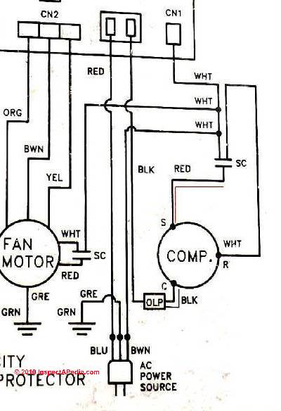
Instructions for electric motor start-run capacitors include the use of starting capacitors for air conditioner compressor motors and other electric motors like pumps. This involves diagnostic checks for start or run capacitors, including how to use a volt-ohm meter...
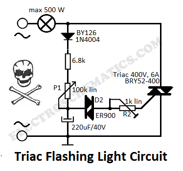
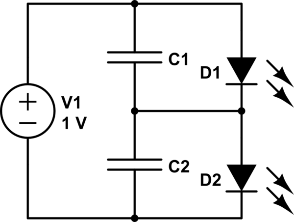
This flashing light circuit utilizes triacs to produce an intermittent light with variable frequency. Additional components include the D1 diode and a semi-adjustable resistor. The flashing light circuit is designed to create a visual indication through intermittent illumination, which can...
For capacitor C3, a 100pF capacitor is placed across resistor R2. The circuit functions similarly to previous configurations, although no explanation is provided. The purpose of this component may be self-evident to experienced users, but it may not be...
This simple circuit tests speakers, microphones, transformers, and voltage. It is essentially a very low-frequency oscillator that generates extremely short, distinctive pulses. The sound produced is easy to hear and allows for precise localization, making it ideal for checking...
The first option is a Zener diode. There are several 2.2V Zener diodes available that could adequately protect the capacitor. However, a significant drawback is that half the energy may be wasted across the diode short. The question arises...
A relay is an effective solution for switching a mains voltage circuit, particularly in applications where long switching times and high currents are present. However, a... A relay is an electromechanical switch that uses an electromagnetic coil to control the...