
Car Anti-Theft Wireless Alarm

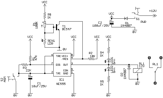
When an intruder attempts to drive the car and moves it a few meters away from the car porch, the radio link between the car (transmitter) and the alarm (receiver) is interrupted. As a result, the FM radio module generates hissing noise. These hissing AC signals are coupled to the relay switching circuit via an audio transformer. The AC signals are then rectified and filtered by diode D1 and capacitor C8, producing a positive DC voltage that provides forward bias to transistor T2. Consequently, transistor T2 conducts, pulling the base of relay driver transistor T3 to ground level. This deactivates the relay, and the alarm connected through the normally closed contacts of the relay is activated. Even if the intruder disconnects the transmitter from the battery, the remote alarm remains active because the absence of the signal causes the receiver to continue producing hissing noise at its output. Therefore, the burglar alarm is fool-proof and highly reliable.
The circuit operates effectively by utilizing a simple yet efficient design. The transmitter, which is typically a miniaturized FM transmitter, is designed to operate within a specific frequency range that corresponds to the receiver's tuning. The use of the CXA1019 module allows for a compact solution that simplifies the overall design while ensuring reliable communication between the transmitter and receiver.
The relay driver circuit is crucial for the operation of the alarm system. Transistor T3 acts as a switch that controls the relay, which in turn activates the alarm. The 10k resistor R5 is essential for providing the correct biasing to T3, allowing it to function effectively when the conditions are met.
Additionally, the audio transformer plays a significant role in coupling the hissing noise generated by the FM module to the relay switching circuit. This ensures that the alarm is triggered appropriately in the event of a breach. The rectification and filtering process performed by diode D1 and capacitor C8 is vital for converting the AC signals into a usable DC voltage that can control the transistors.
Overall, the design of this anti-theft wireless alarm circuit demonstrates a practical application of radio frequency technology in automotive security, providing a reliable means of protecting vehicles from theft. The system's simplicity and effectiveness make it an attractive option for vehicle owners seeking enhanced security measures.This alarm circuit is an anti- theft wireless alarm can be used with any vehicle having 6- to 12-volt DC supply system. The mini VHF FM radio-controlled, FM transmitter is fitted in the vehicle at night when it is parked in the car porch or car park.
The receiver unit of the wireless alarm uses an CXA1019, a single IC-based FM radio module, which is freely available in the market at reasonable rate, is kept inside. Receiver is tuned to the transmitter`s frequency. When the transmitter is on and the signals are being received by FM radio receiver, no hissing noise is available at the output of receiver. Thus transis- tor T2 (BC548) does not conduct. This results in the relay driver transistor T3 getting its forward base bias via 10k resistor R5 and the relay gets energised.
The following is a schematic drawing: When an intruder tries to drive the car and takes it a few metres away from the car porch, the radio link betw- een the car (transmitter) and alarm (receiver) is broken. As a result FM radio module gene-rates hissing noise. Hissing AC signals are coupled to relay switching circ- uit via audio transformer. These AC signals are rectified and filtered by diode D1 and capacitor C8, and the resulting positive DC voltage provides a forward bias to transistor T2.
Thus transistor T2 conducts, and it pulls the base of relay driver transistor T3 to ground level. The relay thus gets de-activated and the alarm connected via N/C contacts of relay is switched on. If, by chance, the intruder finds out about the wireless alarm and disconnects the transmitter from battery, still remote alarm remains activated because in the absence of signal, the receiver continues to produce hissing noise at its output. So the burglar alarm is fool-proof and highly reliable. (Ed: You may have some problem catching the thief, though, if he decides to run away with your vehicle_in spite of the alarm!) We aim to transmit more information by carrying articles.
Please send us an E-mail to wanghuali@hqew. net within 15 days if we are involved in the problems of article content, copyright or other problems. We will delete it soon. 🔗 External reference
Related Circuits

This is a simple alarm circuit that produces a musical tone when water or any conductive liquid comes into contact with the two sensor wires provided. The circuit utilizes four transistors and one melody generator IC (M3482). When water...

The circuit is primarily composed of the integrated voice chip ISD2560. The Winbond ISD2560 is a chip with robust voice recording capabilities, featuring a permanent memory circuit for voice recording. It has a recording duration of 60 seconds and...
When a vehicle is driven on the highway at night, it is essential that the light beam is of high intensity and illuminates the road at a sufficient distance. To achieve optimal visibility during nighttime driving, especially on highways, the...
Car and Motorcycle Battery Tester Circuit. Going camping today often requires bringing various electronic devices for daily activities or entertainment. Typically, a charged lead-acid battery and a power source are essential. The Car and Motorcycle Battery Tester Circuit is designed...
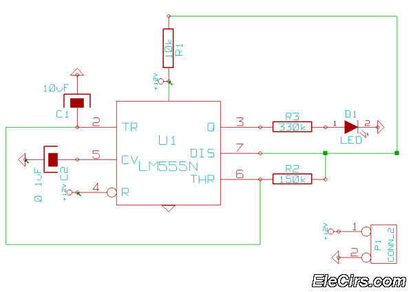
This is a very simple 555 timer circuit that serves as a straightforward theft deterrent, which may be just as effective. The idea is to have a flashing red LED indicate that your car is protected. This device can...
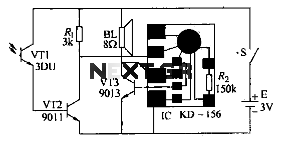
After the gas stove ignition, closing switch S, the circuit is operational. The phototransistor VT1, exposed to flame, remains in a low resistance state. This causes transistor VT2 to enter saturated conduction. Transistor VT3 and the integrated circuit (IC)...