
Fake Car Alarm Circuit using 555 timer

The circuit utilizes a 555 timer IC configured in astable mode to produce a square wave output, which drives a red LED to flash periodically. The frequency of the flashing can be adjusted by changing the resistor and capacitor values connected to the timer.
The basic components of the circuit include the 555 timer IC, a red LED, a resistor, and a capacitor. The LED is connected to the output pin of the 555 timer, while the resistor and capacitor are connected to the discharge and threshold pins, respectively. The values of these components determine the timing characteristics of the flashing LED.
For instance, using a 1 kΩ resistor and a 10 µF capacitor will result in a flashing rate of approximately 0.1 Hz, meaning the LED will turn on for 5 seconds and then off for 5 seconds. This on/off cycle can effectively draw attention to the vehicle, deterring potential thieves.
The circuit can be powered by a 9V battery, providing a compact and portable solution for car protection. The simplicity of the design allows for easy assembly and troubleshooting, making it an accessible project for beginners.
To enhance the effectiveness of the deterrent, additional features such as a motion sensor or a sound alarm can be integrated, providing an even greater level of security. Overall, this simple 555 timer circuit serves as an effective and low-cost solution for vehicle protection against theft.This is a very simple 555 timer circuit,It make a simple theft detterant which may be just as effective. The idea is to have a flashing red led indicate that your car is protected. This device can protect your vehicle from potential thieves.. 🔗 External reference
Related Circuits

The first example utilizes a standard op-amp oscillator circuit to produce a triangular waveform, which is then level-shifted and supplied to a comparator (e.g., LM339) to generate a PWM waveform. It is common for users to prefer using two...
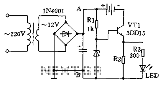
A practical single-tube constant current charger is illustrated, utilizing a transistor (VT1) that plays a crucial role in maintaining a constant current. The current value is determined by the voltage regulator and resistor R2. The general output voltage is...

The following circuit illustrates the sensor circuit diagram for automatic room lights. This circuit is based on the CD4017 integrated circuit (IC) and features the use of two light-dependent resistors (LDRs). The automatic room light circuit utilizes the CD4017 decade...

This dual-polarity, multivoltage power supply can be constructed with a minimal investment. The circuit utilizes 78XX and 79XX series voltage regulators, four 3-A diodes, a 24-30 V, 2-6 A transformer, and eight filter capacitors. The described dual-polarity, multivoltage power supply...

This circuit is the simplest inductive balancing metal detector (IB, Induction Balance) that can be constructed. The LB metal detection method offers satisfactory depth of penetration and effectively distinguishes between iron-based and noble metallic objects. While several metal detectors...

The circuit expands a single 15-pin D-sub VGA output to multiple outputs, allowing for the connection of up to six monitors simultaneously. The input VGA connector is positioned on the left side, while the six output VGA connectors are...