
Car Battery And Alternator Monitor Circuit
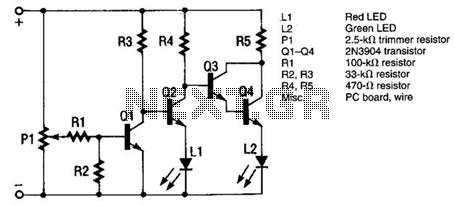
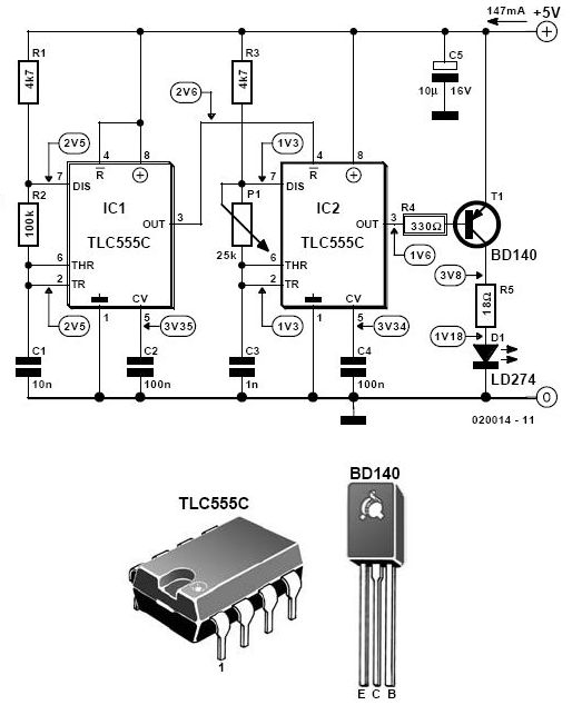
The voltage comparator circuit is designed to monitor the operational status of a car's alternator by comparing the battery voltage against a predefined reference voltage set by the potentiometer PI. The circuit comprises several key components: a voltage comparator, transistors, and indicator LEDs. The voltage comparator continuously assesses the battery voltage level. When the alternator is functioning correctly, the voltage exceeds the reference set by PI, keeping Q1 off. This condition prevents Q2 from conducting, which allows Q3 and Q4 to remain active, thereby powering the green LED L2 to indicate normal operation.
In the event of an alternator failure, the battery voltage drops below the reference level. This change causes Q1 to turn off, which in turn enables Q2 to conduct fully. As Q2 becomes active, it interrupts the conduction of Q3 and Q4, resulting in the green LED L2 turning off and the red LED L1 illuminating to indicate a fault condition.
The circuit's design emphasizes simplicity and effectiveness, allowing for straightforward troubleshooting in automotive applications. The use of LEDs as visual indicators provides immediate feedback to the user regarding the alternator's operational status. The incorporation of a potentiometer for voltage adjustment allows for calibration, ensuring that the system can accommodate variations in battery voltage due to environmental factors or battery health.
Overall, this voltage comparator circuit is a practical solution for monitoring alternator performance, providing clear visual signals that can assist in the maintenance and diagnosis of automotive electrical systems. The monitor is a simple voltage comparator in which a car battery serves as the battery for operation. The input voltage to the comparator is set by adjustment potentiometer PI, which must be adjusted so that the green LED L2 is on when the alternator is operating properly and red LED1 is on when the alternator is inoperative.The circuit operates as follows: When the alternator operates properly, the battery voltage is higher and PI is set so that transistor Ql causes Q2 to be off.
That results in Q3 and Q4 being fully on, thus applying current to green LED L2. If the battery voltage is lowered (alternator inoperative), transistor Ql is turned off. That allows transistor Q2 to turn fully on, applying current to red LED LI, indicating trouble. Once Q2 is on, it causes Q3 and Q4 to go out of conduction. 🔗 External reference
Related Circuits
This circuit includes a Relay Timer Circuit. One of the most commonly used circuits is that of the 555 Timer integrated circuit (IC). The circuit is designed to control a relay based on a timing interval. The Relay Timer Circuit...
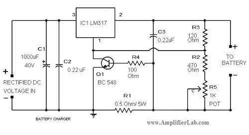
The circuit diagram of a lead-acid battery charger is presented here. The main component of this circuit is the IC LM317. The lead-acid battery charger circuit utilizing the LM317 voltage regulator is designed to efficiently charge lead-acid batteries while providing...
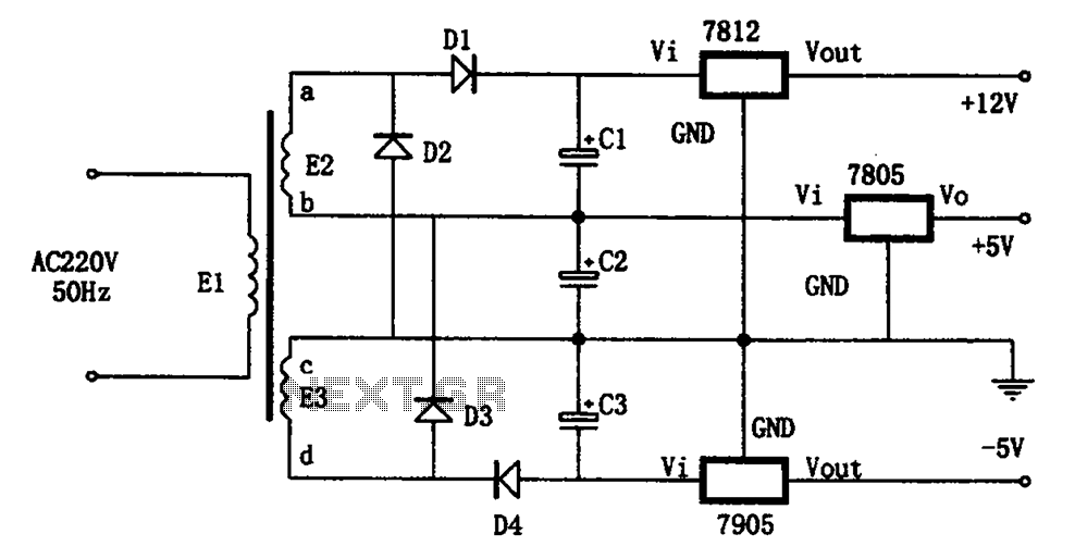
The circuit illustrated in the figure represents a specialized power supply configuration. It is straightforward in design and can be constructed using two identical secondary windings to generate three distinct DC voltage outputs: +5V, -5V, and +12V. The circuit...
This unit would be mounted in a small plastic or preferably metal box, with a 9V battery, level control, a male XLR connector (same as on a mic) and a switch. Current drain is low, since the circuit only...
This timer is designed for individuals seeking to achieve a tan while minimizing excessive exposure to sunlight. A rotary switch allows the user to set the timer based on six classified photo-types. A photoresistor adjusts the preset time value...
This infrared alarm barrier is designed to detect individuals passing through doorways, corridors, and small gates. The transmitter emits an invisible beam of infrared light. When this beam is interrupted by a person, a buzzer connected to the receiver...