
Simple Lead-Acid Battery Charger Circuit
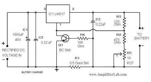
The lead-acid battery charger circuit utilizing the LM317 voltage regulator is designed to efficiently charge lead-acid batteries while providing adjustable output voltage and current regulation. The LM317 is a popular adjustable three-terminal voltage regulator that can output a voltage range from 1.25V to 37V, making it suitable for charging various types of lead-acid batteries.
In this circuit, the input voltage is typically higher than the desired output voltage, often sourced from an AC to DC converter or a rectified power supply. The LM317 requires a minimum input-to-output voltage differential to function effectively, which is generally around 3V. Thus, if charging a 12V battery, the input voltage should be at least 15V.
The configuration of the LM317 in this application involves two resistors, R1 and R2, which set the output voltage according to the formula: Vout = Vref (1 + R2/R1) + Iadj * R2. Here, Vref is approximately 1.25V. By selecting appropriate resistor values, the output voltage can be tailored to match the nominal voltage of the battery being charged.
To ensure safe charging, a current limiting feature is often integrated into the circuit. This can be accomplished by including a sense resistor in series with the load, which allows the circuit to monitor the charging current. If the current exceeds a predetermined threshold, the LM317 will reduce the output voltage, thus preventing overcharging and extending the lifespan of the battery.
Additionally, it is advisable to include a heat sink on the LM317, as it may dissipate significant heat during operation, especially when charging at higher currents. Capacitors are also recommended at the input and output of the LM317 to stabilize the voltage and filter out any noise.
Overall, the lead-acid battery charger circuit using the LM317 is a versatile and effective solution for charging batteries safely and efficiently, with adjustable output parameters to accommodate various battery specifications.The circuit diagram of lead acid battery charger has been described here. The core part of this circuit is the IC LM 317. 🔗 External reference
Related Circuits
This current-limiting circuit, illustrated in this example as part of a small bench power supply, could theoretically be utilized alongside any dual-rail current source. The section of the circuit to the left of the diagram restricts the input current...
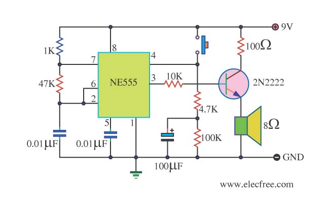
This is a danger beep circuit. It uses a 555 integrated circuit configured as a stable multivibrator that provides a duty cycle of 5% to drive a loudspeaker. The danger beep circuit utilizes the 555 timer IC, a versatile and...
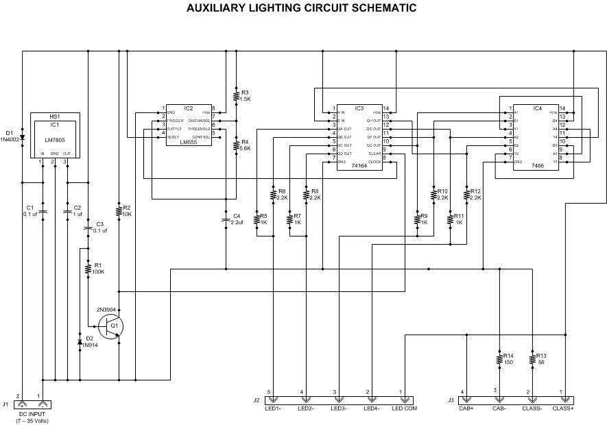
This article outlines a lighting circuit designed to create a glowing firebox effect while providing constant illumination for classification lamps and an interior cab light. It includes comprehensive information necessary for constructing the circuit, such as a detailed schematic,...
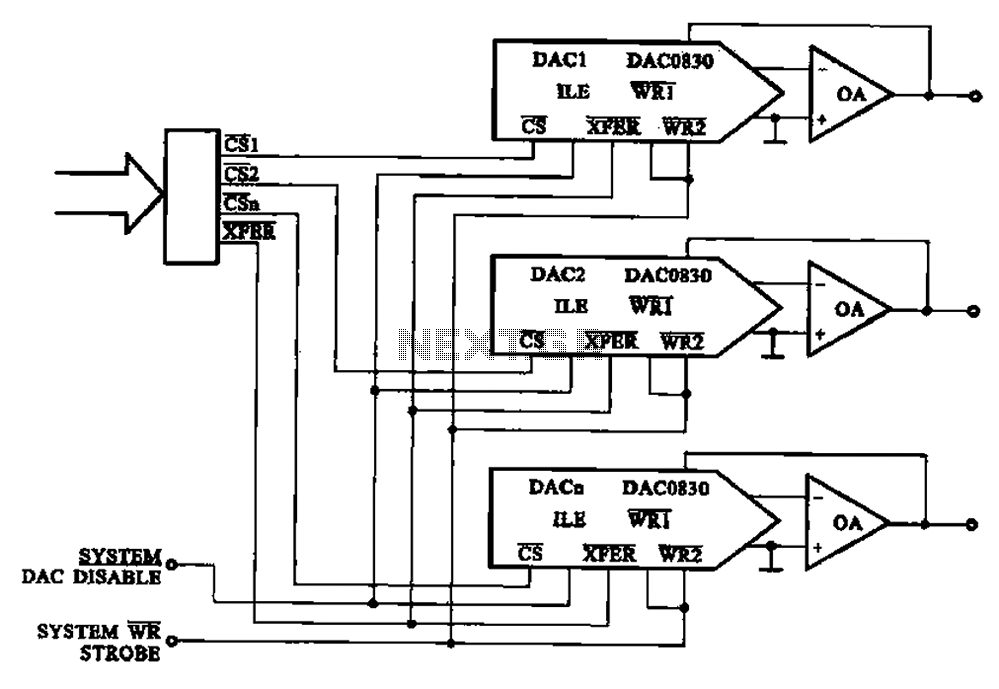
A multi-channel D/A converter circuit is presented, illustrating its fundamental structure. This circuit effectively converts encoded digital signals into multiplexed analog signal outputs. The multi-channel Digital-to-Analog (D/A) converter circuit is designed to facilitate the conversion of digital signals into corresponding...
The 7208 seven-stage decimal counter can be utilized as a frequency counter. It features latch and multiplexing functions, along with direct digital driving circuitry and display driving circuitry. The output frequency of the 7207 IC 6.5536 MHz crystal oscillator...
The primary function of this circuit is to activate a buzzer or a relay whenever the humidity level reaches a specified threshold. The main component is a memory element based on a flip-flop made up of gates and integrated...