
Car Battery Charger
The lead-acid battery charger circuit typically consists of several key components that work together to ensure safe and effective charging. The primary components include a transformer, a rectifier, a voltage regulator, and various protection elements.
The transformer steps down the AC voltage from the mains to a lower AC voltage suitable for charging. This lower voltage is then fed into a rectifier, which converts the AC voltage into DC voltage. A common choice for the rectifier is a bridge rectifier configuration, which utilizes four diodes arranged in a bridge formation to efficiently convert the AC input.
After rectification, the DC voltage may require regulation to ensure that the charging voltage does not exceed the battery's specifications. A voltage regulator, such as a linear regulator or a switching regulator, can be employed to maintain a constant output voltage. This is critical to prevent overcharging, which can damage the battery or reduce its lifespan.
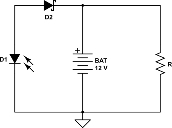
Additionally, the circuit may incorporate protection features such as fuses or circuit breakers to safeguard against overcurrent conditions, as well as diodes to prevent reverse polarity connections. An LED indicator can also be included to signal when the charger is active, providing visual feedback to the user.
The circuit diagram included with the project will illustrate the connections between these components, detailing the input and output terminals, as well as any additional features such as adjustment potentiometers for fine-tuning the output voltage. This project is suitable for hobbyists and professionals alike, offering a practical solution for charging lead-acid batteries efficiently and safely.This charger will quickly and easily charge most any lead acid battery. Electronics project, easy to build, with circuit diagram included.. 🔗 External reference
Related Circuits
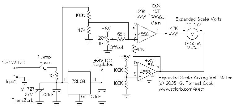
This circuit is designed to measure the voltage of a 12V nominal lead-acid rechargeable battery system. While it was specifically created for solar-powered systems, it is versatile enough for use in automotive or other 12V applications. Lead-acid batteries typically...
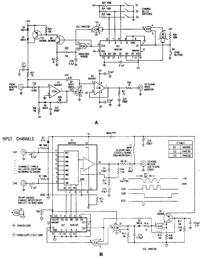
In the video system shown in Figs. A and R, a single coaxial cable transmits power to a remote location, selects one of eight video channels, and returns the chosen signal. This system can select from multiple remote surveillance...
The charger in this project is designed to charge two AA NiMH or NiCd cells of any capacity (as long as they are the same) at approximately 470mA. It will charge 700mAh NiCd cells in about 1.5 hours, 1500mAh...
The circuit utilizes a quad voltage comparator (LM339) as a basic bar graph meter to display the charge status of a 12-volt lead-acid battery. A 5-volt reference voltage is applied to each of the positive (+) inputs of the...
A 12V battery is charged using a solar panel. When the battery reaches 12V, the solar panel is disconnected from the battery, and the load is connected to the battery. The solar panel is reconnected to the battery when...
Photo. This is the test circuit -the basic driver is only two transistors, two resistors, the circuit was evaluated using a white LED, but when it was time to button it up and archive it, I replaced the expensive...
Warning: include(partials/cookie-banner.php): Failed to open stream: Permission denied in /var/www/html/nextgr/view-circuit.php on line 713
Warning: include(): Failed opening 'partials/cookie-banner.php' for inclusion (include_path='.:/usr/share/php') in /var/www/html/nextgr/view-circuit.php on line 713