
Battery Operated LED Lantern
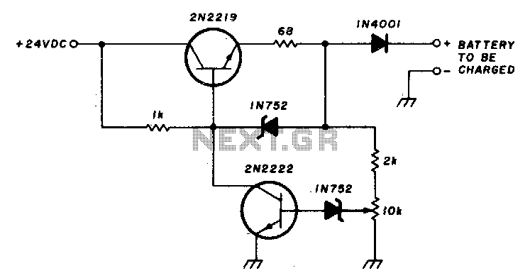
The described test circuit functions as a basic LED driver utilizing two transistors to control the current flow to the LED. The primary components include two NPN transistors, which are configured in a common emitter arrangement to amplify the input signal. The transistors are connected to a pair of resistors that set the biasing conditions and limit the base current to prevent damage to the transistors.
In this circuit, the white LED was initially used for evaluation purposes, providing a high brightness output suitable for flashlight applications. However, for practical implementation, a lower-cost green LED was substituted. The green LED operates at a different forward voltage, which may require adjustments to the resistor values to ensure optimal performance without exceeding the LED's current rating.
An additional consideration in the design is the incorporation of a voltage converter, which allows for the use of a single cell in a two-cell flashlight configuration. This converter steps up the voltage to the necessary level for the LED, enhancing efficiency and extending battery life. The LED assembly replaces traditional incandescent bulbs, offering advantages such as lower power consumption, longer lifespan, and improved durability.
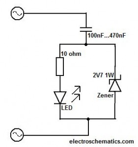
The circuit layout should be carefully designed to minimize parasitic capacitance and inductance, ensuring stable operation. Proper heat dissipation measures must also be considered, especially if the circuit is to be used in high-power applications. Overall, this basic driver circuit is a practical solution for LED-based lighting applications, demonstrating the versatility and efficiency of modern electronic components.Photo. This is the test circuit -the basic driver is only two transistors, two resistors, the circuit was evaluated using a white LED, but when it was time to button it up and archive it, I replaced the expensive white LED with a cheap green one. When Dave and I were kicking around ideas for the best arrangement of components for white led flashlight, Dave suggested putting the voltage converter in place of the second cell in a two cell flashlight, and substitute an LED assembly for the incandesce 🔗 External reference
Related Circuits
This document presents a circuit diagram for a simple and easy-to-construct battery level indicator. Typically, in mobile phones, battery levels are shown in either dot or bar format, allowing users to easily recognize the battery status. The battery level indicator...
This circuit was designed as a warning flasher to alert road users to dangerous situations in the dark. Alternatively, it can act as a bicycle light. The circuit operates by utilizing a light-emitting diode (LED) as the primary visual alerting...
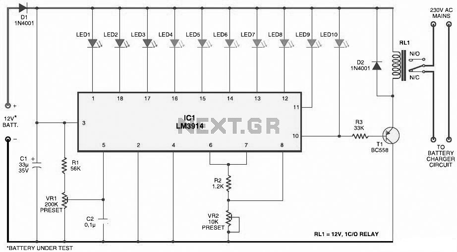
This circuit charges a battery at a rate of 75 mA, allowing the battery to remain in the charger indefinitely until fully charged. Once the battery reaches its full charge, the circuit reduces the current to a trickle rate....
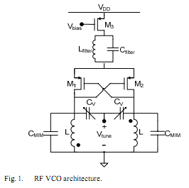
The oscillator is designed to tune from 1.8 GHz to 2 GHz for typical cellular telephony applications. An extended tuning range can be obtained by adjusting the ratio between the varactor capacitance and fixed capacitance in the tank. PMOSFETs...
LED displays consist of arrays of Light Emitting Diodes (LEDs) arranged in various shapes to convey specific information. The operation of LED displays is similar to that of standard LEDs, requiring straightforward connections when sufficient microcontroller pins are available....
This circuit should only be attempted by individuals with a strong understanding of electronic devices. It is connected to a main power source (220V) and poses a risk of high electrical shock. This circuit operates at a mains voltage of...
Warning: include(partials/cookie-banner.php): Failed to open stream: Permission denied in /var/www/html/nextgr/view-circuit.php on line 713
Warning: include(): Failed opening 'partials/cookie-banner.php' for inclusion (include_path='.:/usr/share/php') in /var/www/html/nextgr/view-circuit.php on line 713