
car battery monitor with 3 led
The circuit functions as a battery voltage monitoring system using three transistors and three LEDs to provide visual indications of the battery's voltage level.
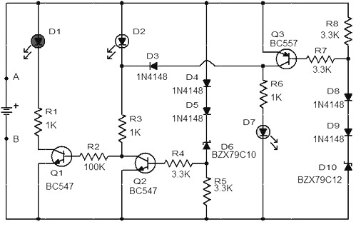
Transistor Q1, configured as a low-side switch, is responsible for monitoring the battery voltage when it falls below 11.5V. In this state, Q1 conducts, allowing current to flow through LED D1, which lights up to indicate a low battery condition. This feature serves as an early warning for users to recharge or replace the battery.
Transistor Q2 is activated when the battery voltage is between 11.5V and 13.5V. In this range, Q2 operates similarly to Q1 but is designed to indicate a nominal battery voltage. When Q2 turns on, LED D2 illuminates, providing a visual cue that the battery is within an acceptable voltage range. This helps users understand that the battery is functioning properly without immediate attention required.
At a voltage of 13.5V, transistor Q3 is engaged, activating LED D3. This indicates that the battery is fully charged or operating at a healthy voltage level. The use of three distinct LEDs allows for quick visual assessment of the battery's state, enabling users to take appropriate actions based on the battery's condition.
The schematic diagram for this circuit typically includes the three transistors, each connected to their respective LEDs, along with resistors to limit current and protect the components. The circuit may also include a voltage divider or reference voltage source to accurately monitor the battery voltage levels. Overall, this design is effective for simple battery monitoring applications, providing clear visual feedback for battery status.When the battery voltage is 11. 5V or less transistor Q1 is turned on and the LED D1 will be bright. When the battery voltage is between 11. 5 and 13. 5 V, the transistor Q2 is turned on and the LED D2 will light up. When the battery voltage is 13. 5V transistor Q3 will be on the D3 and the LED will light. The schematic diagram come from circuit: Car Battery Monitor with 3 LED power supply. Go to that page to read the explanation about above power supply related circuit diagram. 🔗 External reference
Related Circuits
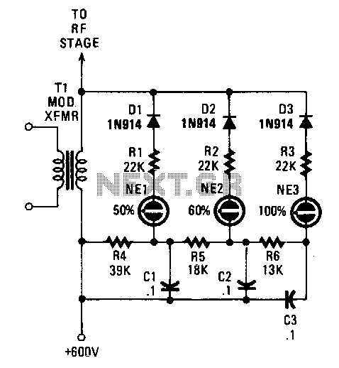
Switching diodes are utilized to activate the neon lamps when negative-peak modulation reaches 50%, 60%, and 100%. To operate the circuit effectively, it is important to monitor the lamps. The 50% lamp should ideally be firing continuously, the 60%...

In many vehicles, the boot light remains illuminated until the lid is fully closed. It is common to inadvertently leave the lid slightly open while unloading, which can lead to a drained battery if the car is not used...

This Outdoor LED Solar Garden Lights project is a hobby circuit for an automatic garden light that utilizes a light-dependent resistor (LDR) and a 6V/5W solar panel. During daytime, the internal rechargeable 6 Volt sealed lead-acid (SLA) battery is...

This car alarm circuit features an 18-second delay for both entrance and exit. It sounds continuously for 6 minutes before automatically turning off the horn and preparing for the next triggering event. The alarm remains activated even if the...
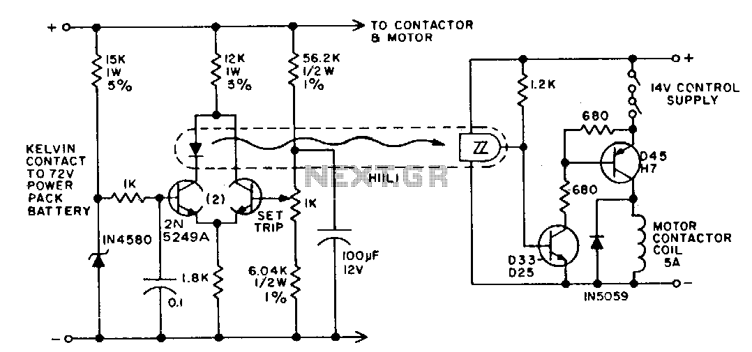
The battery life and operating cost of an electric vehicle are significantly impacted by the overdischarge of the battery. This circuit is designed to provide both a warning and a shutdown mechanism. An electronic switch is connected in series...
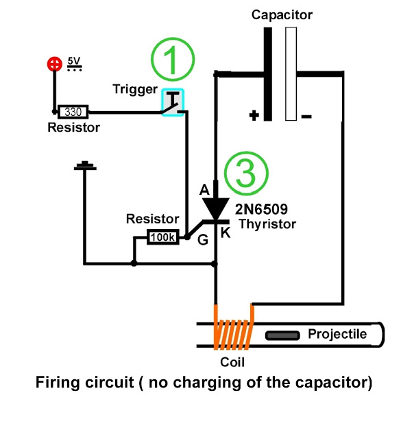
A coil is wound around a non-conductive tube, which serves as the barrel of the coilgun. The tube must be made from a non-conductive material, such as plastic, to prevent the coil's magnetic field from canceling itself out within...