
Car battery tester circuit
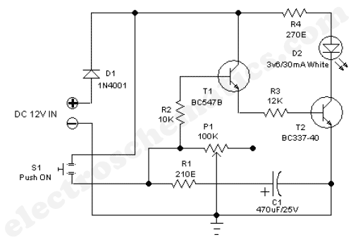
The automatic wiper control circuit is designed to enhance driving safety and comfort by allowing the driver to customize the wiper operation based on environmental conditions. The astable multivibrator configuration of the 555 IC generates a continuous square wave output, which is essential for controlling the timing of the wiper motor. By adjusting the resistance of R2, the duty cycle of the output waveform can be varied, effectively changing the duration for which the wiper motor is activated.
In this circuit, the 555 timer is configured in astable mode, where it oscillates between high and low states. The frequency of this oscillation is determined by the values of resistors R1 and R2, as well as the capacitor C1. The relationship between these components can be expressed using the formula for the frequency of the oscillation. The output from pin 3 of the 555 timer drives a relay or a transistor connected to the wiper motor, allowing it to operate intermittently rather than continuously.
The power supply for this circuit is specified at 12V, which is typical for automotive applications. This ensures compatibility with the vehicle's electrical system. The potentiometer R2 should be rated appropriately to handle the voltage and current levels in the circuit, and it should be mounted in a location that is easily accessible to the driver.
In summary, this automatic wiper control circuit offers an economical and effective solution for adjusting wiper speeds, improving the overall driving experience during adverse weather conditions. By allowing for manual control over the wiper operation, the driver can ensure optimal visibility without the distraction of incessant wiping.In rainy seasons, it is very annoying that wiper of your car wiping instantly all the time. Have you ever think of speed control of the wiper. There are wiper control modules available on the market but most of them are costly. So here is an automatic wiper control circuit which enables you to control your wiper sweep rates from 1 second to 10 sec ond. The heart of this circuit is an astable multivibrator using 555 Ic. We actually change the duty cycle of the square wave to obtain different sweep rates to control the wiper. The output pin 3 of the IC remains high for a time period set by R2. During this time the wiper motor will sweep at rates. The power supply to this wiper control circuit should be 12V. fit the potentiometer R2 anywhere on the dashboard of your vehicle and control the sweep rates according to the intensity of the rain.
🔗 External reference
Related Circuits
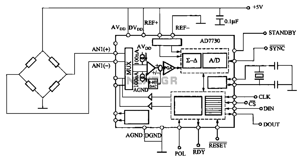
AD7710/7715/7730 multifunction digital sensor signal conditioning integrated circuits (ICs) that combine a digital interface with a control port, a clock generator, a digital filter, amplitude modulation, a programmable gain amplifier, an analog-to-digital (A/D) converter, and additional electrical pathways. The...
The 555 adjustable timer circuit initiates timing upon activation. A green LED illuminates to indicate that the timing process is underway. Once the designated time period concludes, the... The 555 timer IC is a versatile device widely used in various...
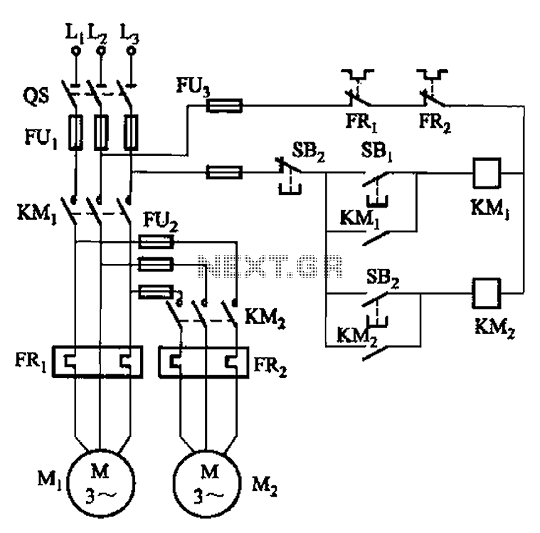
The circuit illustrated in Figure 3-83 demonstrates that the contactor KMi is activated only after it is pulled, which indicates that the motor Mi has started for the first time. Following this, the contactor KM2 is then activated, indicating...
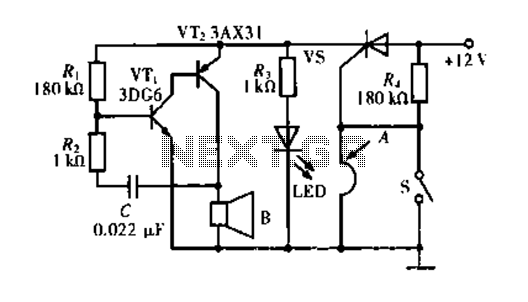
The circuit operates based on a principle where the SCR (Silicon Controlled Rectifier) trigger is grounded, keeping it in the off state. When a burglar triggers the alarm, a voltage is supplied to the SCR trigger, turning it on....
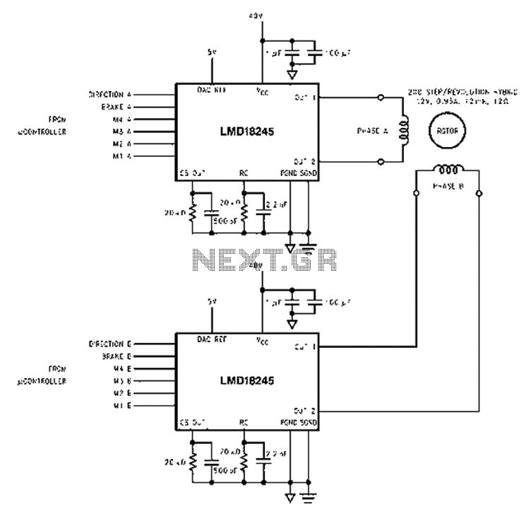
An innovative current detection method eliminates the power loss associated with the sense resistor in series with the motor. A 4-digit analog converter (DAC) facilitates digital control of the motor current path, simplifying the implementation of full, half, and...
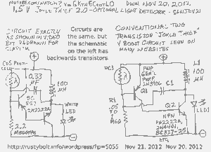
A schematic of a two-transistor Joule Thief was presented in a YouTube video by Sanjev21, which has since been removed. The two-transistor Joule Thief is a compact and efficient circuit designed to extract energy from low-voltage sources, such as depleted...
Warning: include(partials/cookie-banner.php): Failed to open stream: Permission denied in /var/www/html/nextgr/view-circuit.php on line 713
Warning: include(): Failed opening 'partials/cookie-banner.php' for inclusion (include_path='.:/usr/share/php') in /var/www/html/nextgr/view-circuit.php on line 713